3330
On-coil B0 shimming with a flexible coaxial coil element at 3 T1High Field MR Center, Center for Medical Physics and Biomedical Engineering, Medical University of Vienna, Vienna, Austria, 2Department of Radiology, A.A. Martinos Center for Biomedical Imaging, Massachusetts General Hospital, Harvard Medical School, Charlestown, MA, United States
Synopsis
The combination of highly flexible RF coils and on-coil shimming is an interesting concept, in particular for applications in body parts that have strong inter-patient variability, such as breast, thorax or abdomen. The well-known AC/DC approach on rigid standard loop coils involves many bulky RF chokes and would therefore not be suitable for flexible coil elements. In the presented approach coaxial coils are used instead, where no segmenting capacitors and correspondingly no RF chokes are required. We demonstrate that this conceptual design shows good RF performance and the created magnetic fields for shimming are in good agreement with analytical calculations.
Introduction
B0 shimming with local coils has become a useful tool in improving the patient specific susceptibility-induced inhomogeneities. In contrast to shim coil inserts [1] and other multi-coil (MC) shim arrays [2], the approach of using the same wire loop for both DC shim current and RF receive [3] has been successful in solving the space constraints in bore.Coaxial coil elements [4] [5] [6] offer high flexibility and can, therefore, be form-fitted to the individual patient anatomy, increasing the filling factor compared to conventional coils and thereby achieving optimal SNR.
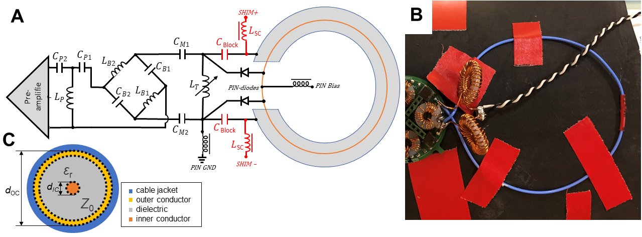
The combination of on-coil shimming and highly flexible coil elements is an interesting yet challenging topic. In this work, we present a first step in this direction by investigating design options that maintain the full flexibility of coaxial coils and integrate on-coil shimming capability at the same time. By employing coaxial elements with one gap, a closed loop can be formed by either the inner conductor or by the cable shield, depending on the placement of the RF coil port. This closed loop can then be used for B0 shimming by only adding two RF chokes directly at the RF coil port, which can be effectively integrated within the coil interface and therefore do not limit flexibility.
Methods
We built and evaluated a flexible 85 mm diameter coil element made of coaxial cable (Molex 047SC-2901, Lisle, IL, USA), which corresponds to a self-resonance of close to 123.2 MHz. The loop is connected to an interface board with a tuning inductor, active detuning circuit, and matching network with onboard low-noise preamplifier (MwT MSM-123281, Microwave Technology, Inc., Fremont, CA, USA). In contrast to most published coaxial coil designs [4] [5] [6], the coil port was located at the gap of the outer conductor. A controlled shim current of 1 A DC was fed on the coaxial cable shield with a linear power supply (BASEtech BT-305) located outside the scanner room. Two toroidal chokes with 18 mm diameter and 32 turns of 1mm diameter enamelled copper wire wire were inserted at the feed port to block RF signals on the DC pathway and avoid interactions with the resonant coaxial element.The loop was tuned and matched to 50 Ω at 123.2 Mhz using a vector network analyzer (Keysight Technologies E5071C, Santa Rosa, CA, USA). Qloaded and Qunloaded were measured using a decoupled (S21: -75dB) double pick-up probe on a phantom.
MR data were acquired on a 3T MRI scanner (Prisma Fit, Siemens Healthineers, Erlangen, Germany) and a 5.3 liter cylindrical phantom with 3.75g NiSO4 x 6H2O + 5g NaCl per 1000g H2O (10606530 K2305, Siemens Healthineers, Erlangen, Germany). Field maps were reconstructed from gradient echo phantom images (TR=961ms, TE1/TE2 = 961ms/5ms/9ms, flip angle=60°, voxel=2x2mm, SL=2mm, matrix=128x128). The B0 field created by the local shim loop was calculated from the difference in phase between an acquisition without shim current applied and with a DC current of 1A. Phase images for both echo times were unwrapped and transformed to Hz per Ampere [7] [8].
Results
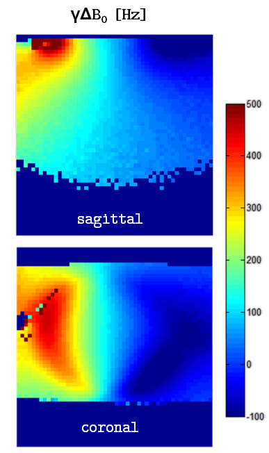
The Q-ratio = Qunloaded/Qloaded for the coaxial loop was 110/41 = 2.68 without shim chokes, and 100/39 = 2.56 (-4.4%) with added chokes, showing negligible added losses due to the shimming capability.The shim loop created a ωΔB0 of about ±300 Hz at about 2 cm from the conductor with 1A DC applied, as shown in Fig. 2, with the positive lobe where the loop’s magnetic field is parallel to the main static field, and vice versa. Analytical calculation using Biot-Savart’s law (http://lampx.tugraz.at/~hadley/physikm/apps/biotsavart.en.php) for a distance of 2 cm from the coil conductor yields 350 Hz, for 2.5 cm distance it would be 258 Hz.
Discussion and Conclusion
The measured shim field is in excellent agreement with analytical calculation. The advantage of the proposed design is that no lumped components need to be introduced along the flexible section of the loop, which does not make it necessary to bridge any distributed RF capacitors or safety fuses. The only added hardware are two RF chokes that can be mounted on the coil interfacing PCB. It was shown that the insertion of these two chokes does not degrade the coil’s Q significantly. Another advantage of the presented design is that the DC current flows on the shield of the coaxial cable, which has a much higher cross-section than the inner conductor, allowing for higher shimming currents without causing heating of the loop.The main challenges for future work on flexible arrays with integrated shimming are related to the dynamic calculation of optimized shim currents, in particular the tracking of coil orientations and positions.
In conclusion, we have demonstrated that it is possible to use coaxial coils as building blocks for flexible arrays with integrated on-coil B0 shimming capability.
Acknowledgements
This work was supported by Austrian National Bank grant #17980 “FlexShim”.References
[1] J. W. Pan, K. M. Lo and H. Hetherington, "Role of very high order and degree B0 shimming for spectroscopic imaging of the human brain at 7 Tesla," Magnetic Resonance in Medicine, vol. 68, no. 4, pp. 1007-1017, 2012.
[2] C. Juchem, T. W. Nixon, S. McIntyre, V. O. Boer, D. L. Rothman and R. A. de Graaf, "Dynamic multi-coil shimming of the human brain at 7 T," Journal of Magnetic Resonance, vol. 212, no. 2, pp. 280-288, 2011.
[3] J. P. Stockmann, T. Witzel, B. Keil, J. R. Polimeni, A. Mareyam, C. LaPierre, K. Setsompop and L. L. Wald, "A 32-channel combined RF and B0 shim array for 3T brain imaging," Magnetic Resonance in Medicine, no. 75 (1), pp. 441 - 451, 2016.
[4] B. Zhang, D. K. Sodickson and M. A. Cloos, "A high-impedance detector-array glove for magnetic resonance imaging of the hand," Nature Biomed. Eng., 2018.
[5] T. Ruytenberg, A. Webb and I. Zivkovic, "Shielded-coaxial-cable coils as receive and transceive array elements for 7T human MRI," Magn. Reson. Med., pp. 1-12, 2019.
[6] M. S. Mollaei, C. C. van Leeuwen, A. J. E. Raaijmakers and C. R. Simovski, "Analysis of high impedance coils both in Transmission and Reception regimes," IEEE Transactions on Medical Imaging, vol. 8, pp. 129754-129762, 2020.
[7] F. Maier, D. Fuentes, J. S. Weinberg, J. D. Hazle and R. J. Stafford, "Robust Phase Unwrapping for MR Temperature Imaging using a Magnitude-sorted List, Multi-clustering Algorithm," Magnetic Resonane in Medicine, vol. 73, pp. 1662-1668, 2015.
[8] B. Dymerska, B. A. Poser, M. Barth, S. Trattnig and S. D. Robinson, "A method for the dynamic correction of B0-related distortions in single-echo EPI at 7 T," Neuroimage, vol. 168, pp. 321-331, 2018.
Figures