3117
Inhomogeneity and ramping effects in field-cycled quantitative molecular MRI1Physics and Astronomy, Western University, London, ON, Canada, 2Medical Biophysics, Western University, London, ON, Canada, 3Robarts Research Institute, Western University, London, ON, Canada
Synopsis
Delta relaxation enhanced magnetic resonance (dreMR) is a field-shifting quantitative molecular imaging method. The dreMR method may be used to produce images with signal proportional to concentration of contrast agents with longitudinal relaxivity dispersion. Here we find that field inhomogeneities and ramping periods, which were previously ignored, cause significant errors in dreMR images. These errors include apparent non-zero signal from dispersion-free tissue, and apparent change in signal due to contrast agents. We show that these effects can be mitigated by use of an improved homogeneity design method, and increased slew rates.
INTRODUCTION
Current medical imaging trends show a growing need for quantitative molecular imaging in preclinical studies. Thus far, positron emission tomography (PET) has been the prevailing method but has an associated radiation dose resulting in undesirable effects in longitudinal studies.1 Delta relaxation enhanced magnetic resonance (dreMR or “dreamer”) is a contrast-enhanced MRI method for quantitative molecular imaging. The dreMR technique uses a B0 insert coil to shift the strength of the static field in a pulse preparation phase of a pulse sequence. Using contrast agents with longitudinal relaxivity (r1) dispersion, images taken at different field strengths can be subtracted, resulting in signal proportional to the concentration of these agents.2 This subtraction is weighted by the different field strengths to cancel out dispersion-free signal. In development of the dreMR method and design of previous dreMR coils,2,3 it was assumed that field homogeneity is unimportant for the dreMR system, and effects of ramping periods were also ignored. Here, we find that field inhomogeneities, and these ramping periods have significant effects on dreMR images and that the improved homogeneity design method we recently developed4 can reduce these effects.METHODS
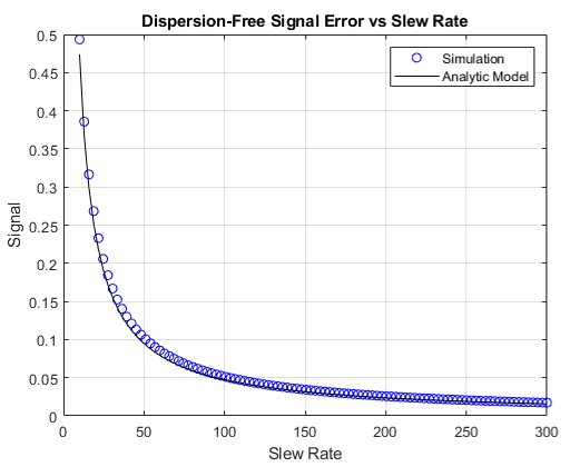
To see inhomogeneity effects analytically, we use the original dreMR subtraction where the images now differ in field with their weightings by the given inhomogeneity. We apply this method in MATLAB to various concentration distributions of the contrast agent VivoTrax using its r1 dispersion data and simulated field maps given by dreMR coil designs. Artificial noise consistent with real dreMR images is added to these simulations. Ramping effects require a new set of Bloch equations, where longitudinal field strength varies in time, and therefore so does r1 in the presence of contrast agent. We consider only the longitudinal magnetization as dreMR is unaffected by behavior of the transverse. This is solved numerically in MATLAB using ode45 for the ramping periods, and solved analytically using the assumptions that ramping field strength is linear in time, r1 is linear with Bz, and overall ramping time is small, so we ignore terms of O(Δt2) or higher.RESULTS
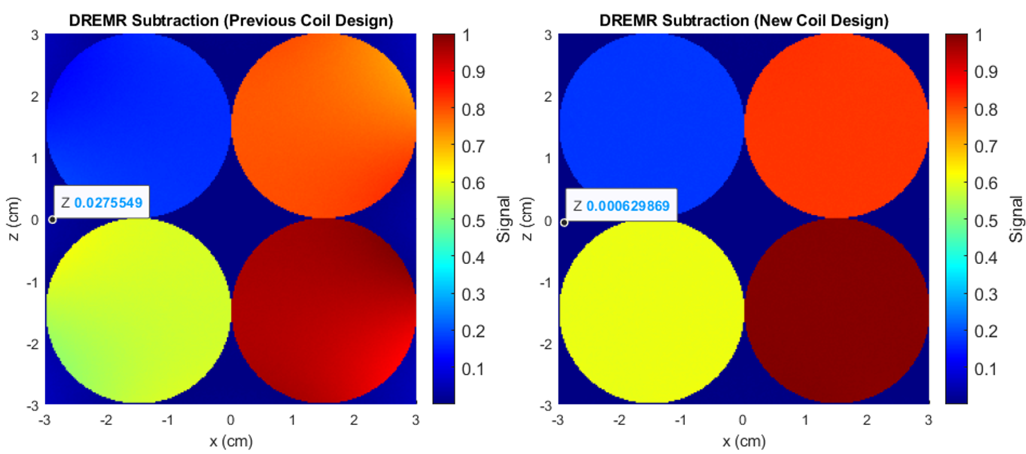
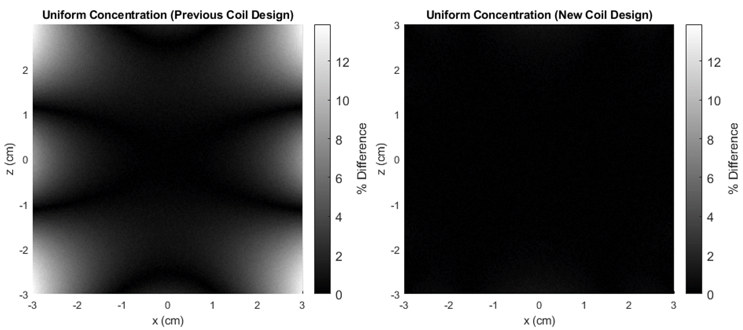
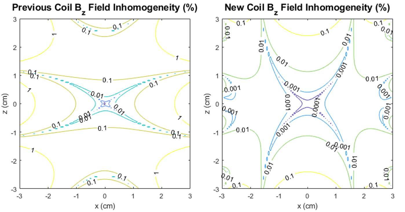
Dispersion-free signal in the presence of inhomogeneities is given analytically through (1), where, ΔB* is the dreMR field with some inhomogeneity. A simulated dreMR subtraction with an inhomogeneous coil, and one of our new coil designs can be seen in Figure 1. Here, cylinders of various VivoTrax concentrations are included in the domain. The same simulation for each coil is shown in Figure 2 where concentration of VivoTrax is homogenous across the domain. The field contours for each coil are given in Figure 3. Dispersion-free signal accounting for a ramping period is given analytically through (2), where ξ is the dreMR coil slew rate, and Δt2 the flat top duration of the dreMR pulse. A comparison of this model with ode45 calculations is given for various slew rates in Figure 4.$$(1) I_0~=2B_0 (\Delta B-\Delta B^*)/(B_0^2-\Delta B^2)$$
$$(2) I_0~=(2M_0B_0/T_1)(\Delta B^2/(B_0^2-\Delta B^2))(1/\xi)exp(-\Delta t_2/T_1)$$
DISCUSSION
Inhomogeneities in the dreMR field shift were found to result in improper cancelling of signal from dispersion-free pixels, and artefacts in signal from contrast agents. These effects result from a difference between expected field in the subtraction weighting, and the actual field at a given point. The shading effects seen in Figure 1, are clearly caused by field inhomogeneities as seen by comparison of Figures 2 and 3. The effect was seen to produce a large difference in signal, reaching a percent difference of 14% in the example of Figure 2. Using our new design method,4 we can improve homogeneity and minimize these effects as seen in Figures 1 and 2. Ramping effects were also found to result in improper cancelling of signal from dispersion-free tissue, and a change in signal from contrast agents. These effects can be minimized by increasing slew rate. While decreasing ΔB can also minimize this effect, doing so decreases signal from contrast agents and causes a loss of contrast.CONCLUSION
Field inhomogeneities can lead to shading artefacts in dreMR images, and signal from dispersion-free regions. These effects can be minimized by using a layer of specifically placed, field-correcting windings within a dreMR coil. The ramping periods of dreMR pulses result in signal from dispersion-free regions and a change in signal from contrast agents, but these effects can be mitigated by using a high slew rate. By using our improved homogeneity design method and a high slew rate, we can noticeably improve quality of images from this quantitative molecular imaging method.Acknowledgements
The authors would like to acknowledge financial support from NSERC, the Ontario Research Fund, and the NSERC Canada Graduate Scholarship - Masters.References
1. Hildebrandt I, et al. Anesthesia and Other Considerations for in Vivo Imaging of Small Animals. ILAR Journal. 2008;49(1):17-26.
2. Alford J, Rutt B, Scholl T, et al. Delta relaxation enhanced MR: Improving activation-specificity of molecular probes through R1 dispersion imaging. Magnetic Resonance in Medicine. 2009;61(4):796–802.
3. Harris C, Handler W, Araya Y, et al. Development and optimization of hardware for delta relaxation enhanced MRI. Magnetic Resonance in Medicine. 2013;72(4):1182–1190.
4. McCready M, Handler W, Chronik B. Improving homogeneity in delta relaxation enhanced magnetic resonance using boundary element method. ISMRM AGM. 2020;3312.
Figures