3115
RF sinc pulse distortion compensation using multiple square pulses at 1 MHz.1Department of Radiology and Biomedical Imaging, Yale School of Medicine, New Haven, CT, United States
Synopsis
The response times of RF coils in MRI are long when operating at low B0 field, making it difficult to achieve the desired pulse shape in the coil. Compensation pulses are shown that were optimized using a series of square pulses. Both the duration and amplitude of the compensation elements were calculated with Q-factor which was calculated from the ring-down time measured using a sniffer coil. The SNRs of the echo signal acquired using compensated pulse was compared with those of signal obtained with uncompensated pulses and showed significant improvements of 51.5%.
Purpose
In low field MRI, the recovery time for an RF coil's is long because it is proportional to the quality factor of the coil (Q-factor), and inversely proportional to the resonance frequency1. The ring-down time of a square pulse can be shortened by applying a damping pulse which is 180° out-of-phase with main pulse2. Similarly, the rise time can be shortened by applying pre-emphasis pulse with greater amplitude2. However, unlike with a rectangular pulse, the amplitude of a sinc pulse is not constant. When the bandwidth of the sinc pulse is wide, its amplitude change quickly. As a result, the actual pulse applied to the RF coil is often distorted and delayed. In this work, we demonstrate a method for calculating an input pulse consisting of a series of square pulses designed to compensate the sinc pulse.Theory
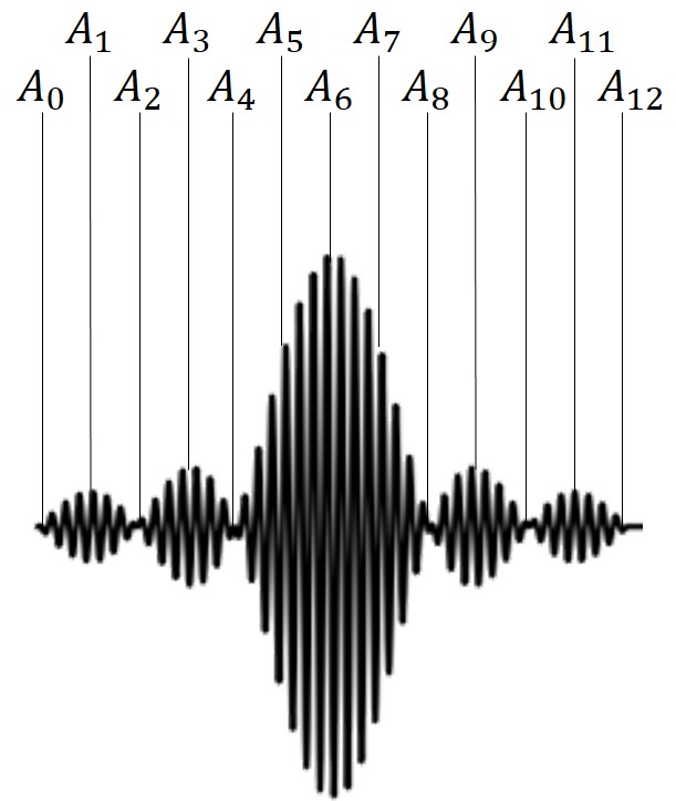
Figure 1 shows an example of an input sinc pulse. The number of samples ($$$N_S$$$) in the signal can be defined as $$$N_S=4iN_0+1$$$, where $$$N_0$$$ indicates the number of zero crossings on each side of the center before truncation, and i is integer. Then, sampled points include all peaks and zero crossing points. For example, for the sinc with $$$N_0=3$$$ and $$$i=1$$$, $$$N_S$$$ is equal to 13 and the peak and zero amplitude points are included in the sampled points as shown in Fig. 1.When a square pulse is applied with peak voltage of $$$V_1$$$ which satisfies the equation below, the amplitude of the actual signal is $$$A_1$$$ at $$$t_1$$$ ($$$t_n=n\Delta t$$$). $$V_1=\frac{A_1}{1-e^{-\frac{\omega}{2Q}\Delta t}}.$$ If a square RF pulse is not applied during the time interval between $$$t_1$$$ and $$$t_2$$$, the amplitude of the actual signal decays. In order to make the amplitude to $$$A_2$$$ at $$$t_2$$$, a square pulse with peak voltage of $$$V_2$$$ should be applied to the RF coil. $$$V_2$$$ is defined as:$$V_2=\frac{A_n-V_1(1-e^{-\frac{\omega}{2Q}\Delta t})e^{-\frac{\omega}{2Q}\Delta t}}{1-e^{-\frac{\omega}{2Q}\Delta t}}.$$Similarly, the peak voltage ($$$V_n$$$) of the square pulse needed to compensate for the $$$n$$$th sampled signal is given by the following general form, $$V_n=\frac{A_n-\sum_{k=0}^{n-1}{V_k(1-e^{-\frac{\omega}{2Q}\Delta t})e^{-\frac{\omega}{2Q}\Delta t(n-k)}}}{1-e^{\frac{\omega}{2Q}\Delta t}}.$$
Methods
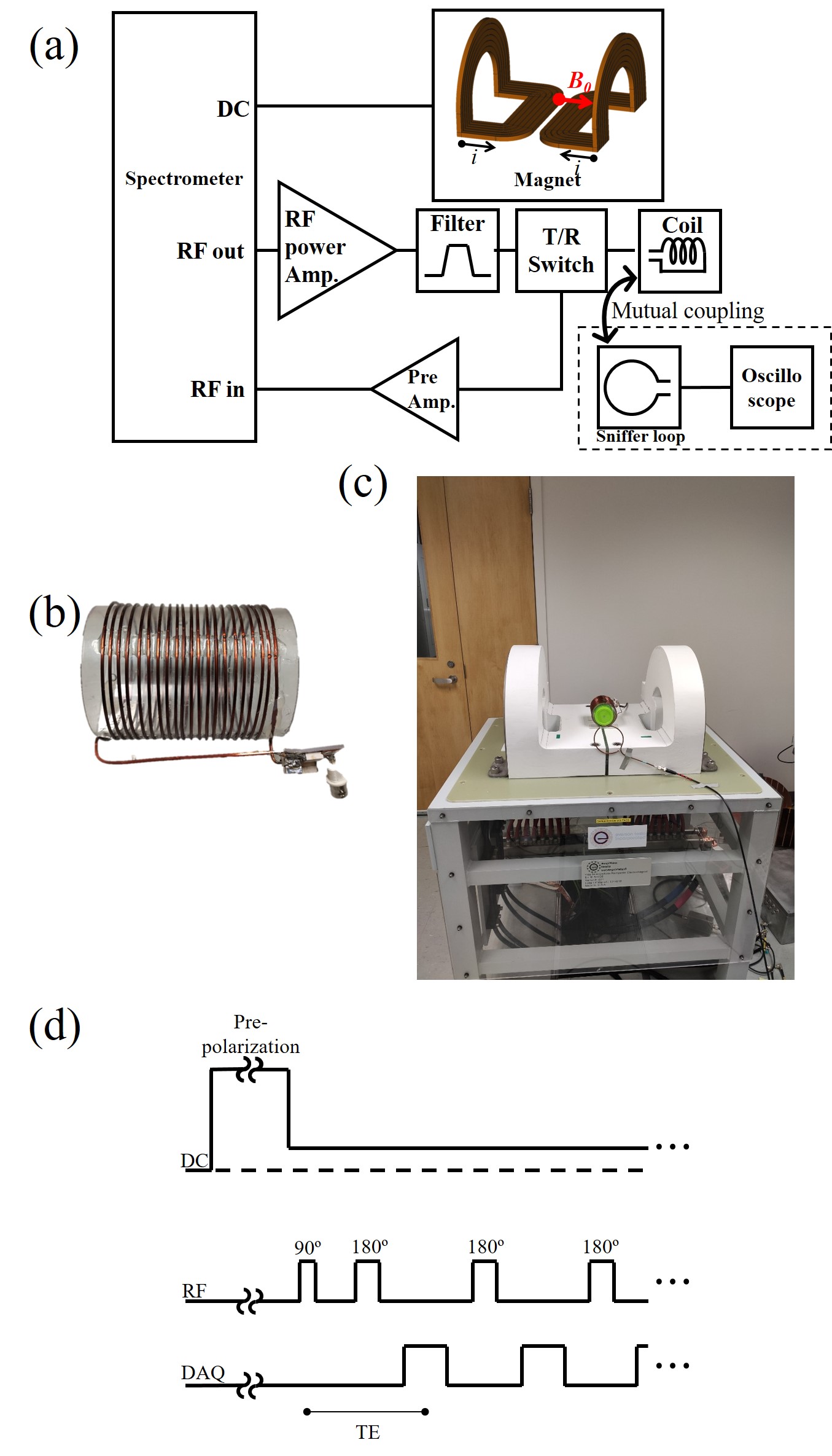
All experiments were carried out on an open, table-top, MRI scanner3. Figure 3a shows the schematic representation of the major system on the scanner and the major interconnections. The MRI system consists of two main components: a two-element electromagnet, and an RF system. Since the electromagnet generates a non-uniform polarizing B0 field, slice selective excitation can be performed without additional gradient coils. The RF solenoid coil is tuned to 1 MHz (23.4 mT) and generates an alternating B1 magnetic field perpendicular to B0. The RF coil also detects the NMR signal from the sample. From the ring-down signal of the measured pulse with sniffer coil, the Q-factor was calculated using the equation4:$$Q=\frac{\pi N}{ln(2)}=4.53N,$$where N is number of cycles it takes to halve the amplitude. Sinc pulses with different bandwidths (30 kHz, 90 kHz, and 150 kHz) were applied to the RF coil. The actual signals of them were measured using a sniffer loop connected to an oscilloscope. The amplitude and duration for the compensated sinc pulse were calculated for different $$$N_S$$$ (13, 25, and 37) with measured Q-factor. Then, compensated sinc pulses were applied to the RF coil and the actual pulses were measured. 1H echo trains of the water phantom were obtained using compensated sinc pulses. Figure 2d shows the diagram of applied sequence (pre-polarization time: 5 s, TR: 6.5 s, TE: 1.5 ms, number of echoes: 1000, Averages: 32). A pulse with double amplitude of 90° pulse was applied as the 180° pulse. The SNR of the NMR signal was also compared with and without using RF pulse distortion compensation.Results
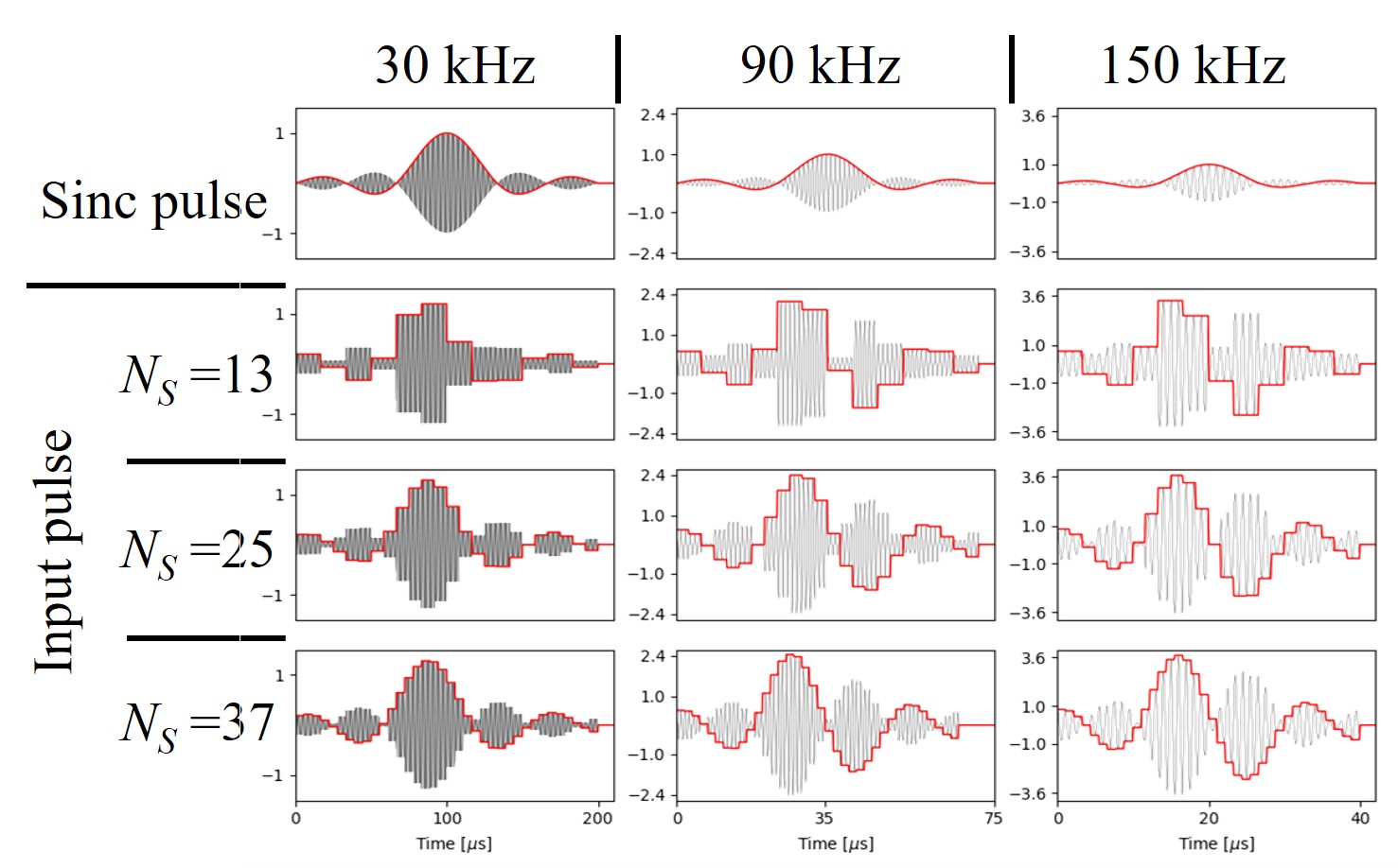
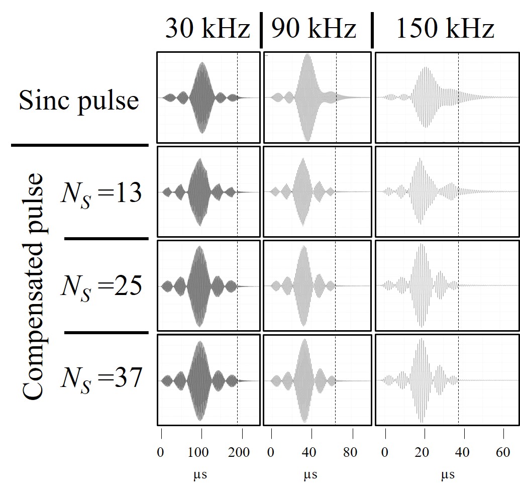
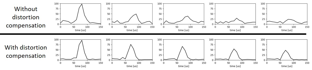
Figure 3 shows the calculated amplitude for compensating the sinc pulses for the different bandwidths. Since the amplitude changes rapidly for the wide band pulse, higher amplitudes are required for the compensation. Figure 4 shows the measured actual pulses when the sinc and compensated sinc pulses were applied. The ring-down of the RF coil also affects the shape of the sinc pulse, especially for broad band pulses. Figure 5 shows the 1H NMR signal from a water phantom. The x axis shows time in microseconds and y axis shows the normalized signal intensity. The compensated sinc pulses was calculated with $$$N_S=37$$$. The SNR of the NMR signal were 14.0 and 27.2, without and with dostortion compensation respectively.Discussion
In low field MRI, applied RF pulses can be distorted due to long RF coil recovery times. This study demonstrates that compensation pulses (including the required duration and amplitude of such a pulse) can be calculated utilizing the measured Q-factor, and these compensation pulses lead to RF shapes closer to the desired output. The SNR of the echo signals obtained using compensated sinc pulse was 51.5% higer relative to that obtained using the original uncompensated pulse indicating substantial improvement with this compensation strategy.Conclusioins
It was demonstrated that sinc pulse shapes could be improved by applying compensation RF pulses at the RF input. Echo trains 1000 echoes long were acquired using these pulses at low readout field B0. Improvement in the echo SNR was demonstrated by using RF pulse compensation.Acknowledgements
No acknowledgement found.References
1. M. I. Hrovat, S. Patz, “Pulse sequence for elimination of RF receiver coil ring down,” in Proc. 9th Annu. Meet. Int. Soc. Magn. Res. Med., Glasgow, Scotland, Apr.21-27 2001.
2. J. Z. Zhen, K. T. O’Neill, E. O. Fridjonsson, P. L. Stanwix, and M. L. Johns, “A resistive Q-switch for low-field NMR systems,” J. Magn. Reson., vol. 287, pp. 33-40, Feb. 2018.
3. R. T. Constable, C. Rogers III, B. Wu, K. Selvaganesan, and G. Galiana, “Design of a novel class of open MRI devices with nonuniform B0, field cycling, and RF spartial encoding,” in Proc. 27th Annu. Meet. Int. Soc. Magn. Res. Med., Montreal, Canada, May 10-13, 2019.
4. I. Giangrandi, “Measuring the Q-factor of a resonator with the ring-down method,” viewed 1 Apl. 2020, <http://www.giangrandi.ch/electronics/ringdownq/ringdownq.shtml>, Dec. 2014.
Figures