3112
Magnetic fields produced by simple coils inside finite-length cylindrical passive shields with end-caps1Sir Peter Mansfield Imaging Centre, University of Nottingham, Nottingham, United Kingdom, 2School of Physics and Astronomy, University of Nottingham, Nottingham, United Kingdom
Synopsis
Cylindrical shields formed from material of high permeability are commonly used in providing low-magnetic field environments for experimental research. Cylindrical coils are often sited inside such shields to produce controlled patterns of field variation, but interaction of the coils with the mu-metal distorts the fields. Here we show how to analytically calculate the fields that are produced by simple coils inside a finite-length, cylindrical mu-metal shield with end-caps, and report experimental measurements on two different coils (loop and saddle), demonstrating excellent agreement with the theory. Optimal spacings of Helmholtz-type coils inside finite-length shields are also derived using the analytic expressions.
Introduction
Cylindrical shields formed from material of high permeability, such as mu-metal, are commonly used in providing a low-magnetic field environment for experimental research. Applications of mu-metal shields in magnetic resonance, include zero and ultralow magnetic field NMR experiments [1], the SABRE-Sheath approach to hyperpolarisation using parahydrogen [2] and shielding of electron beams in MR LINACs [3]. Cylindrical coils are often sited inside such shields, either to allow nulling of residual fields, or to produce controlled patterns of field variation inside the shield, but the interaction of the coils with the mu-metal distorts the fields. Although the field perturbation can be found using finite or boundary element methods [4], an analytic formulation can provide greater insight. Here we show how to analytically calculate the fields that are produced by simple coils inside finite length mu-metal shields with end-caps [5], and report experimental measurements demonstrating the veracity of this approach.Theory
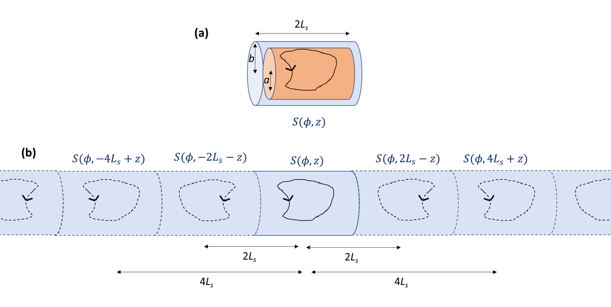
Figure 1a shows the shield and coil geometry. The coil is described by the stream function, $$$ S(\phi,z)$$$ (where $$$\mathbf{J}(\phi,z)=\boldsymbol{\nabla} S \times \boldsymbol{\hat{\rho}}$$$ represents the coil current distribution) on a cylinder of radius $$$a$$$. The shield has radius $$$ b \geq a$$$ and length $$$2L_s$$$. If the shield is formed from material of high permeability, $$$\mu_r$$$, at low frequency the magnetic field is perpendicular to the inner surface of the shield to satisfy the boundary conditions (deviations being of order $$$1/\mu_r$$$). Applying this condition at the inner cylindrical surface ( $$$ \rho = b$$$ ) yields$$ \begin{Bmatrix} B_z(\rho>a,\phi,z) \\ B_z(\rho<a,\phi,z) \end{Bmatrix} = \frac{ia\mu_0}{2\pi}\sum_{m=-\infty}^{\infty}\int_{-\infty}^{\infty}\mathrm{d}k\ e^{im\phi}e^{ikz}k^2 \begin{Bmatrix} I'_m(ka)\left(K_m(k\rho)-\frac{I_m(k\rho)K_m(kb)}{I_m(kb)}\right) \\ I_m(k\rho)\left(K'_m(ka)-\frac{I'_m(ka)K_m(kb)}{I_m(kb)}\right) \end{Bmatrix} S_m(k) \; \;\; [1]$$ where $$ S_m(k)=\frac{1}{2\pi}\int_{0}^{2\pi}\mathrm{d}\phi\int_{-\infty}^{\infty}\mathrm{d}z\ e^{-im\phi}e^{-ikz}S(\phi,z) \; \;\; [2]$$ is the two-dimensional Fourier transform of the stream function and $$$I_m(x)$$$ and $$$K_m(x)$$$ are modified Bessel functions. The 2nd term in the curly brackets characterises the effect of the shield. To force the field to be normal to the end-caps we use the method of images, which generates an infinite series of reflections of the current distribution (Figure 1b) whose effects can be taken into account by replacing $$$ S_m(k)$$$ in Eq. 1 with $$ S'_m(k)=S_m(k)\left(1+\sum_{n=1}^{\infty}2\cos(4nkL_s)\right)+S^{*}_m(k)\left(\sum_{n=1}^{\infty}2\cos(2(2n-1)kL_s)\right) \; \;\; [3]$$ where * indicates complex conjugation. Similar expressions have been derived for the radial and azimuthal components of the magnetic field [5].
Methods
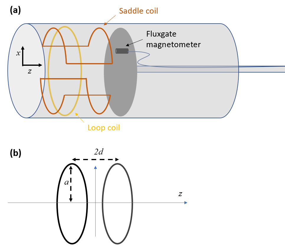
To test the analytic expressions, we made measurements of the magnetic fields generated by two simple coils: [i] a single loop and [ii] a pair of saddle coils with a length-to-diameter ratio of one, (arranged to generate a field $$$B_x$$$) inside a cylindrical shield, and compared the results to theoretical predictions. Coils were mounted inside a cylinder of 1 m length and 30 cm radius with end-caps, formed from mu-metal of 1.5-mm thickness (Figure 2a). Coils were driven at 2 Hz with peak-to-peak current of less than 100 mA. Field variation inside the cylinder was measured using a single-axis fluxgate magnetometer, which could be moved to different axial and radial positions with respect to the coil and re-oriented to measure the axial and radial field components. Measurements were made with each coil located at different distances from one end-cap in order to vary the magnitude of the reflections. Measurements were also made in the absence of the shield. Field variations were calculated using Eqs. [1-3] (and corresponding expression for the radial field [5]), using the stream function for each coil. To illustrate the utility of these equations, we also evaluated the optimal separation of the two loops of a Helmholz-type coil (Figure 2b) in cylindrical shields of varying length.Results
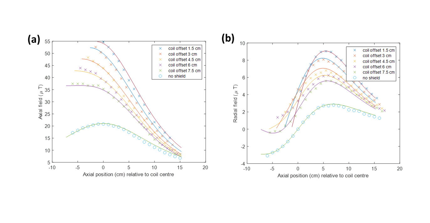
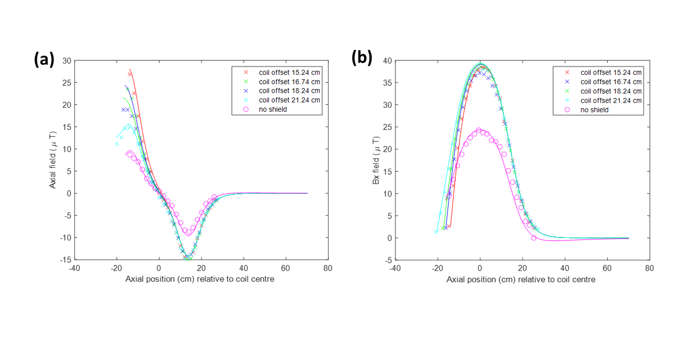
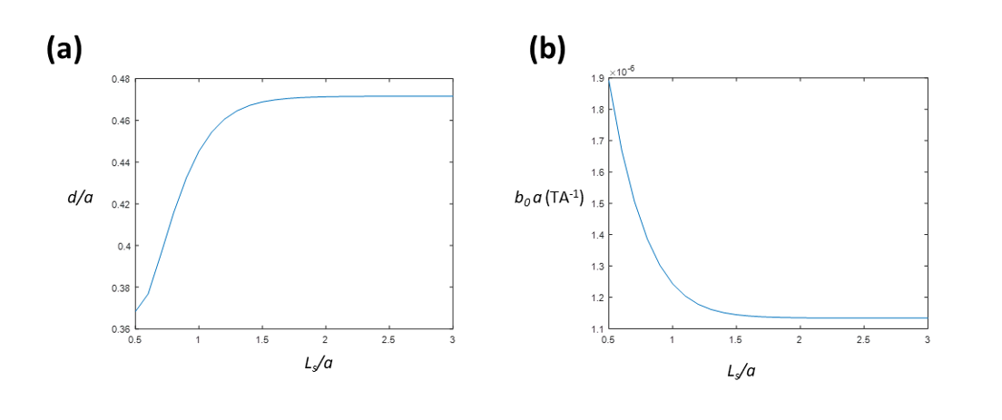
Figure 3 shows the variation with axial position of the measured and calculated axial (on axis) and radial (off-axis by 4.5 cm) fields with z-position for the single loop coil (5 turns; diameter30 cm) when the loop is offset from one end-cap by distances ranging from 1.5-7 cm. Figure 4 shows similar plots of the axial (5 cm off axis) and x-oriented (on-axis) fields for the saddle coil (5 turns; diameter 27 cm; length 27 cm) when the centre of the saddle coil is offset from one end-cap by distances ranging from 15.2- 21.2 cm. Figure 5a shows how the optimal length-to-diameter ratio, $$$d/a$$$, of a Helmholtz-type coil centred inside a finite-length cylindrical screen varies with screen half-length, $$$L_s/a$$$ when the coil is wound on the inner surface of the shield ($$$b = a$$$). The variation of the field per unit current with $$$L_s/a$$$ for optimal coils is shown in Figure 5b.Discussion
There is excellent agreement between the calculated and measured fields in all cases (Figures 3 and 4), indicating that the analytic expressions fully characterise the interaction between the coil and shield at low frequency. The cylindrical surface of the shield acts to enhance the field for the coils considered here. Increased proximity of the coils to the end-cap enhances the axial field, and reduces the radial field near the mu-metal surface, as expected. The analytic expressions allow the optimisation of a Helmholtz-type coil accounting for the interaction with a finite-length shield. Figure 5 shows that the optimal loop-separation is reduced and the field strength is enhanced by the cylindrical shield and these effects are enhanced as the length of the shield decreases.Acknowledgements
We acknowledge support from the UK Quantum Technology Hub Sensors and Timing, funded by the Engineering and Physical Sciences Research Council (EP/M013294/1).References
1. Tayler, M.C.D., T. Theis, T.F. Sjolander, J.W. Blanchard, A. Kentner, S. Pustelny, A. Pines, and D. Budker, Invited Review Article: Instrumentation for nuclear magnetic resonance in zero and ultralow magnetic field. Review of Scientific Instruments, 2017. 88(9).
2. Theis, T., M.L. Truong, A.M. Coffey, R.V. Shchepin, K.W. Waddell, F. Shi, B.M. Goodson, W.S. Warren, and E.Y. Chekmenev, Microtesla SABRE Enables 10% Nitrogen-15 Nuclear Spin Polarization. Journal of the American Chemical Society, 2015. 137(4): p. 1404-1407.
3. Whelan, B., S. Kolling, B.M. Oborn, and P. Keall, Passive magnetic shielding in MRI-Linac systems. Physics in Medicine and Biology, 2018. 63(7).
4. Zetter, R., A. Makinen, J. Iivanainen, K.C.J. Zevenhoven, R.J. Ilmoniemi, and L. Parkkonen, Magnetic field modeling with surface currents. Part II. Implementation and usage of bfieldtools. Journal of Applied Physics, 2020. 128(6).
5. Packer, M., P.J. Hobson, N. Holmes, J. Leggett, P. Glover, M.J. Brookes, R. Bowtell, and T.M. Fromhold, Optimal Inverse Design of Magnetic Field Profiles in a Magnetically Shielded Cylinder. Physical Review Applied, 2020. 14(5).
Figures