3106
"RF transparent" local B0 shim coil1Vanderbilt University Institute of Imaging Science, Nashville, TN, United States, 2Department of Radiology and Radilogical Science, Vanderbilt University Medical Center, Nashville, TN, United States
Synopsis
Multiple coils shimming technology has been demonstrated as a promising approach to reduce the B0 inhomogeneity in MRI. However, strong coupling arises when local DC coils are placed close to the imaging area and RF coils. To solve this problem, we proposed a novel local DC shim coil that has little effect on the RF coils, which we called "RF transparent" DC coil. This concept was validated by EM simulation, bench test, and MR experiments. The RF transparent concept will bring much more freedoms to DC coil design (such as many turn and irregular shaped).
Purpose:
Multiple coils shimming technology has been demonstrated as a promising approach to reduce the B0 inhomogeneity in MRI [1-4]. One technology is to share the coil conductor with the Rx coil (Rx-only or Tx/Rx) and use RF chokes to separate the RF signal and the DC current. The other method is to use separate local DC coils. The latter method is beneficial in that much fewer bulky RF chokes are required, shim coils' geometry and layout are not limited by those of RF coils and the multiple turns could be easily achieved. However, strong coupling arises when DC coils are placed close to the imaging area and RF coils. To solve this problem, we proposed a novel local DC coil that has little effect on the RF performance, which we called the "RF transparent" DC coil.Methods:
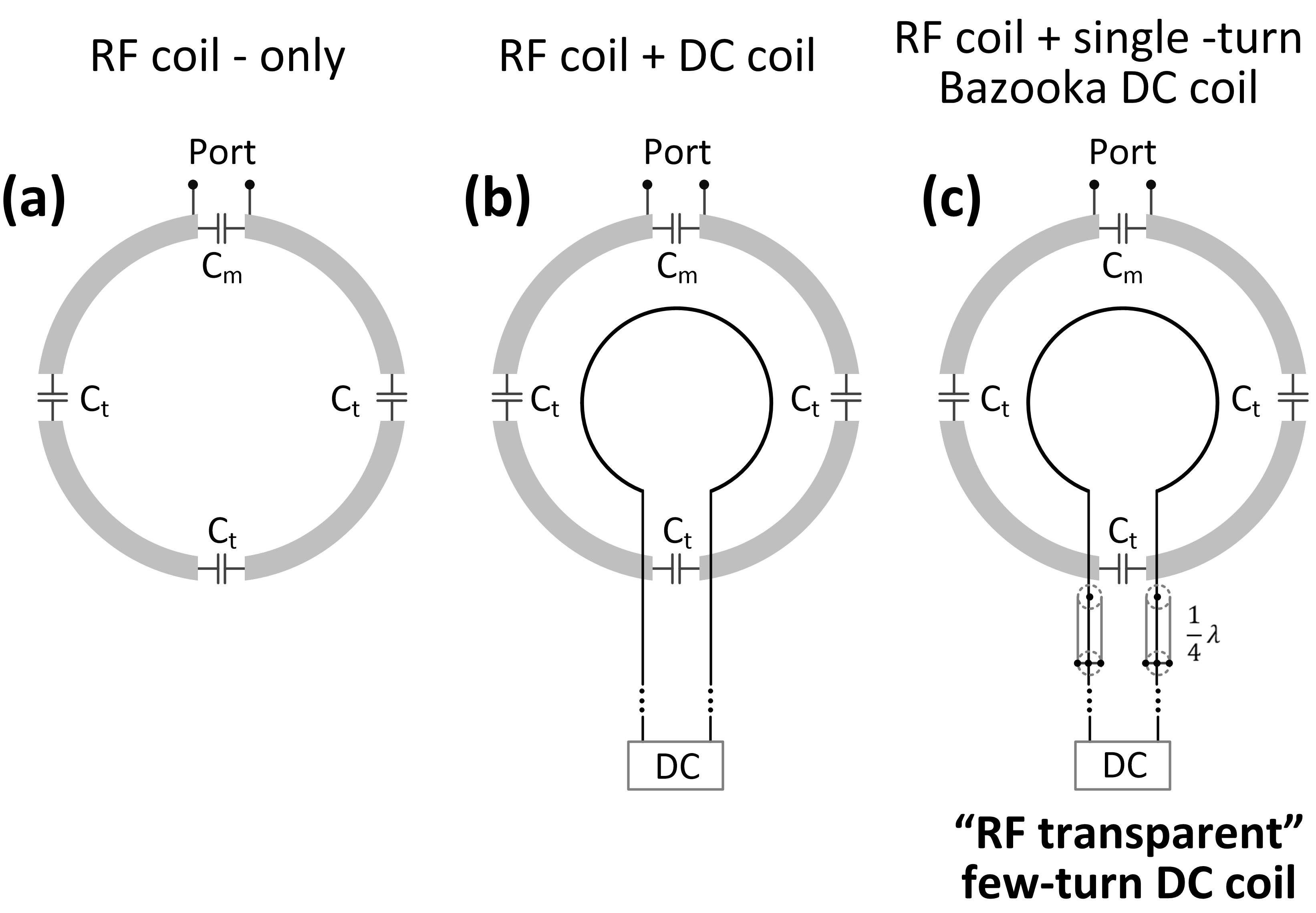
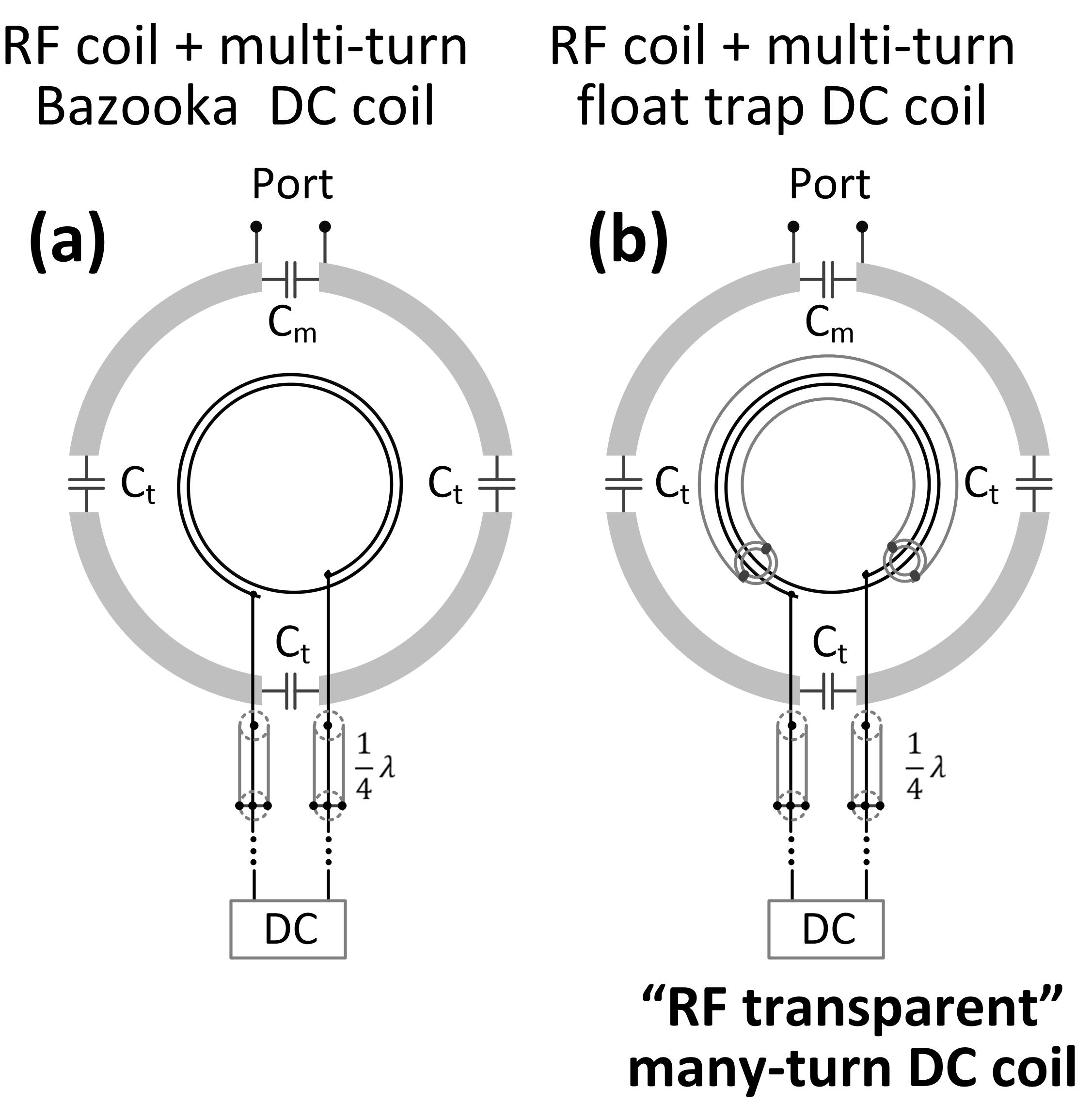
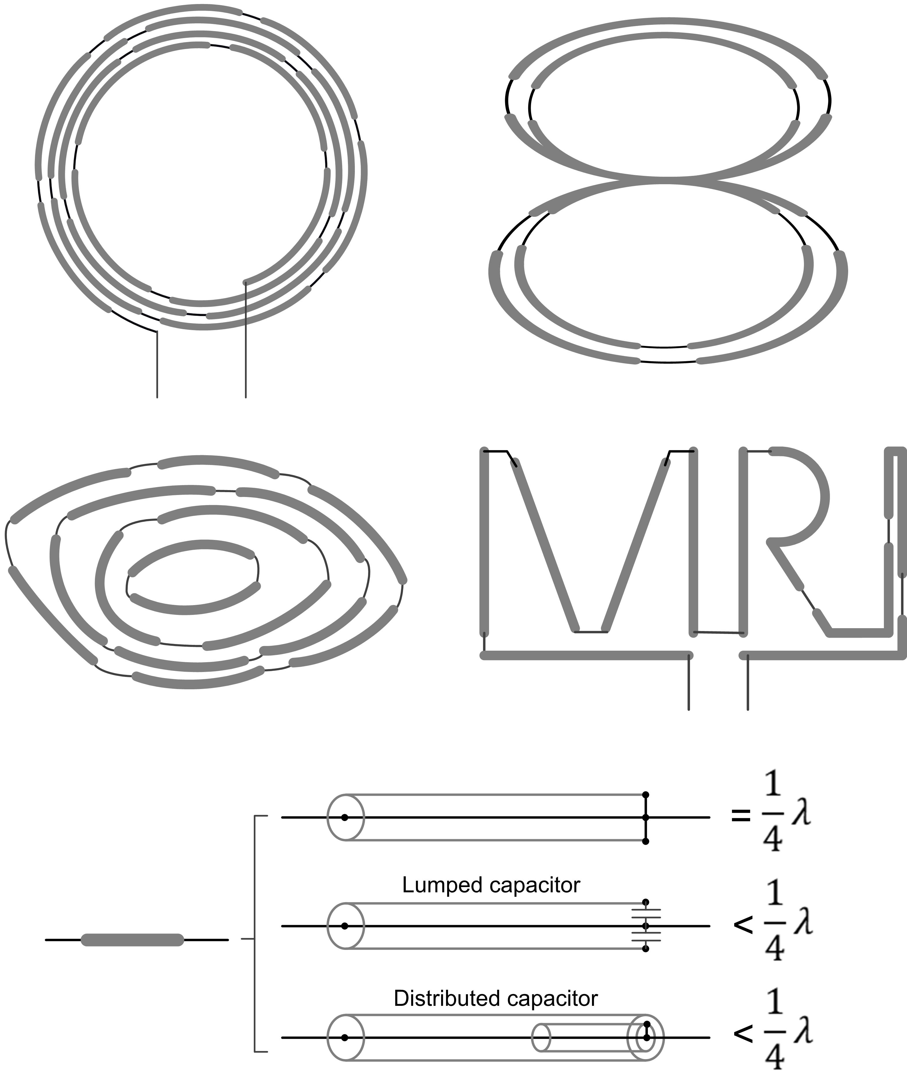
Concept:When DC coils have only one or few turns, their self-resonate frequency is usually far away from RF frequency. Therefore, breaking one point is sufficient to avoid the interaction with RF coil. Figure 1c illustrates the Bazooka-feedline design [5] that realizes intrinsic RF breaking without chokes. For many-turn DC coils, however, it may still resonate close to the RF frequency even the feed port is broken (Figure 2a). To solve this problem, we introduce the "float trap" [6] (Figure 2b) which is expected to break every turn that goes through it. Such Bazooka-feedline and float trap designs are aiming to provide high RF impedance at DC coil and make it “transparent” to the RF field.
EM Simulation, Bench test and MR experiments
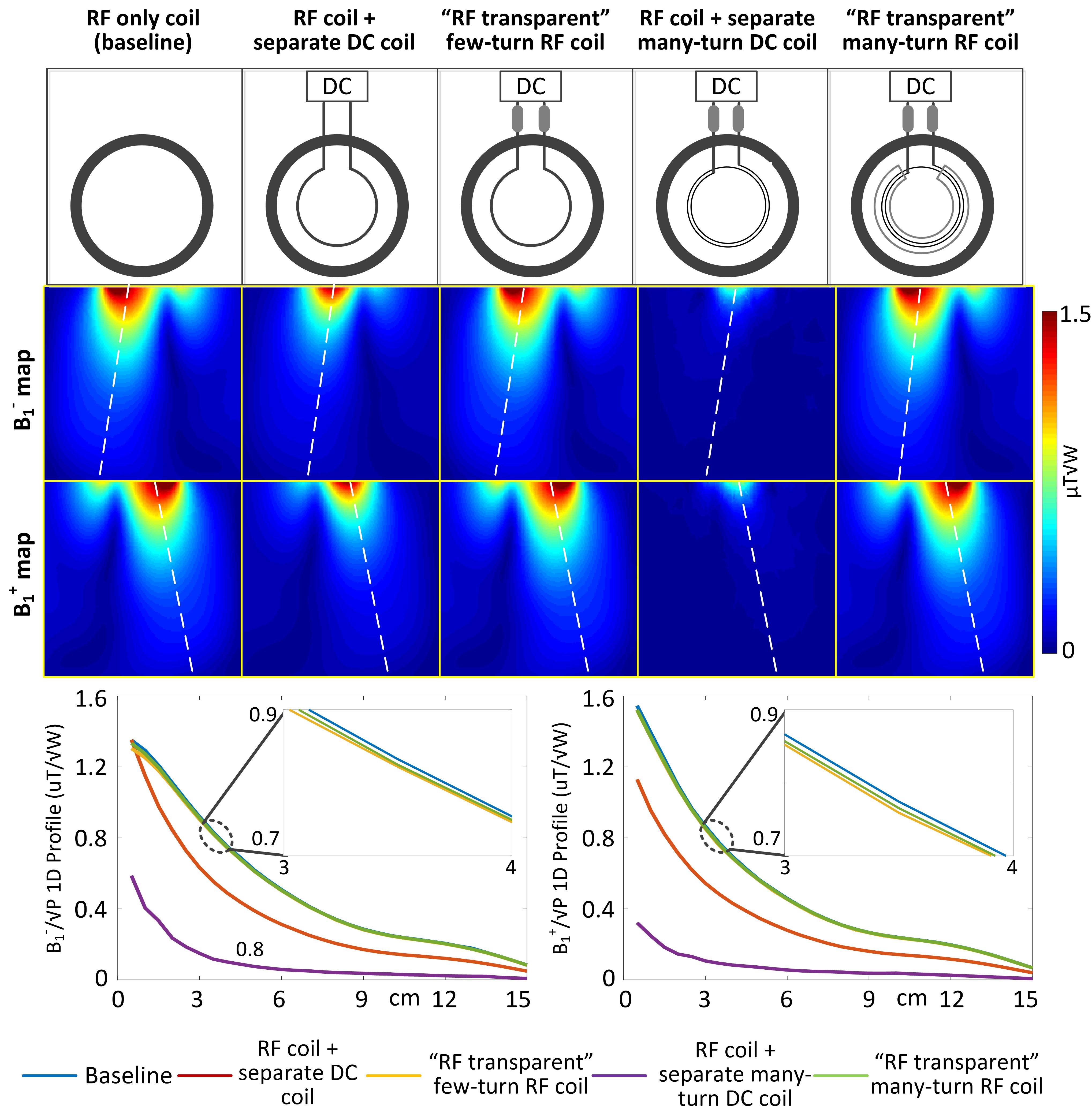
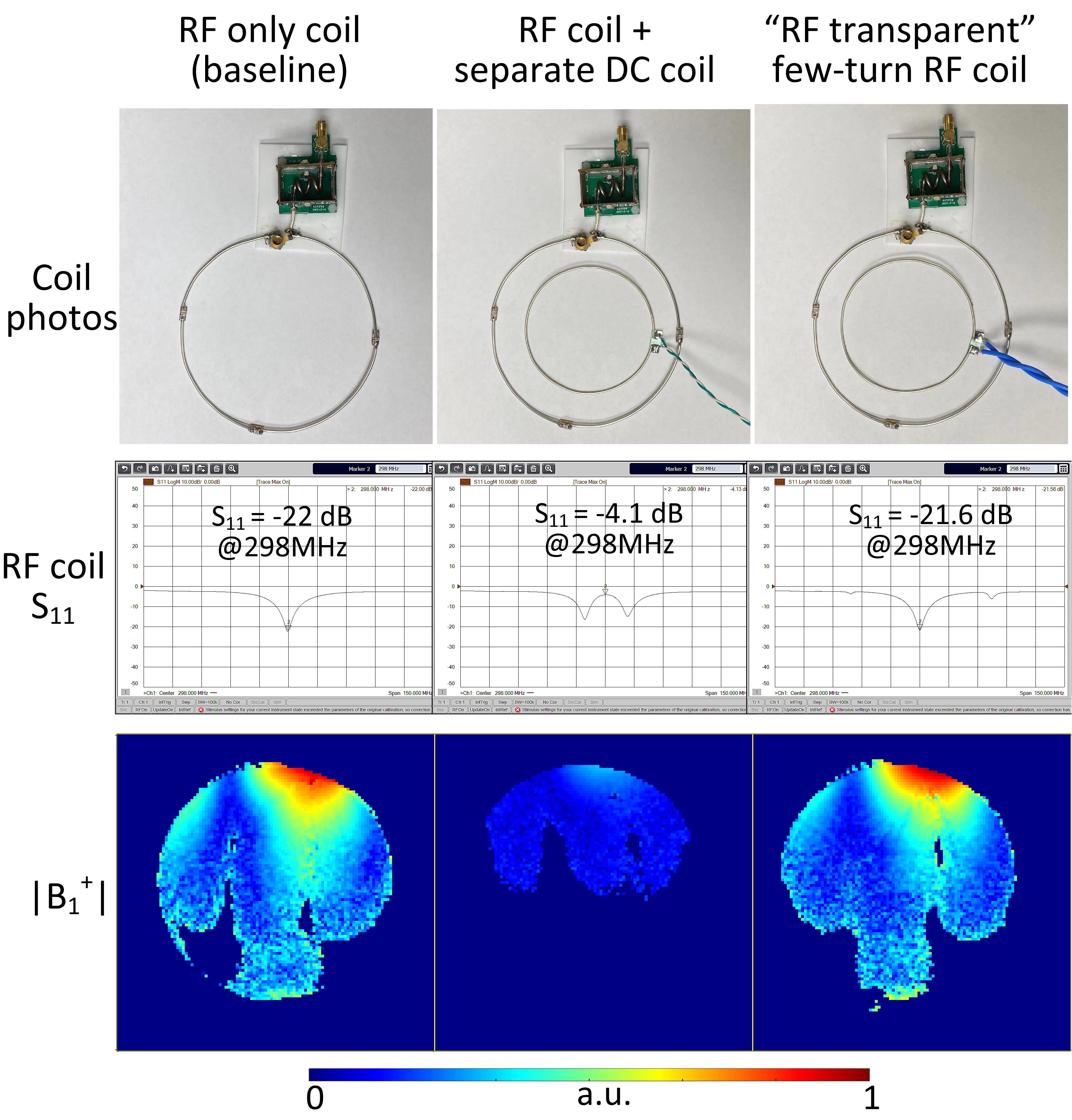
To fully demonstrate the “RF transparent” concept, we investigated the worst case where the DC coil resonates near the RF frequency and is placed concentrically with RF coil. All coils mentioned in Figures 1 and 2 were simulated in the Ansys HFSS. These coils were designed for 7T (298MHz). RF coil has a diameter of 10 cm, with three distributed capacitors for tuning and one trimmer capacitor for matching. DC coil has a diameter of 6 cm and was placed 1 cm above the RF coil. They were placed 1cm above a large cube phantom. Both the transmit field efficiency (B1+/√W) and the receive sensitivity (B1-/√W) were investigated. To validate the simulation results, an RF coil, a DC coil without any decoupling/detuning treatments, an “RF-transparent” DC coil were fabricated. Three sceneries were investigated here: (1) RF-only coil, (2) RF coil + DC coil (no decoupling/detuning), (3) RF coil + “RF transparent” DC coil. Reflection coefficients (S11) of the RF coil with and without the DC coils were measured with Keysight E5071C Vector Network Analyzer. Axial B1+ maps (central slice, with the same input power) were measured with DREAM method on a 7T human whole-body scanner (Philips Healthcare, Best, Netherlands).
Results:
Figure 3 shows simulated B1+ and B1- fields of RF coil in different sceneries. For the single-turn DC coil without decoupling/detuning, it decreases B1+/B1- efficiency by 41.1/42.4% at a 5-cm-deep region. This B1+/B1- can be recovered to 98.2/97.9% of those using RF-only coil by employing the Bazooka-feedline “RF-transparent” design. When moving to many turn DC coil, however, it could self-resonate near the RF frequency even with high impedances at the feed port. As shown in Figure 3, the B1+/B1- efficiency was reduced by up to 87.1/82.5%. As expected, this significant B1 decrease can be avoided by using the float trap “RF-transparent” design since the trap forms a high impedance in every turn of the DC coil. Similar to the simulation results, the single-turn DC coil destroy the resonate of the RF coil, with up to 68% B1+ decrease (Figure 4b). While the “RF transparent” DC coil affects little on the RF performance, with almost the same B1+ field as that of RF-only coil (0.9% increase, Figure 4c).Discussions:
Another desired feature of the add-on circuit/component on the DC coil is that they should be self-shielding and not distort ΔB0 field locally. This is obviously true for both the Bazooka-feedline and float-trap designs since they are either broken or isolated from the DC path. Although the coupling between the RF coil and DC coil can be reduced by adding massive RF chokes, it will make the whole system bulky, DC lossy, and even impractical in many-turn coils. In addition to the circular or square-shaped loops, the “RF transparent” coil will enable designs with irregular shapes that solely focuses on the B0 shimming ability (Figure 5).Conclusion:
We proposed novel “RF transparent” local B0 shim coil designs that have minimal crosstalk with RF coils. This concept was validated by EM simulation, bench test, and MR experiments. The RF transparent concept will bring much more freedoms to DC coil design, such as many-turn DC coils close to the imaging area to improve the ΔB0 efficiency and irregular wire patterns that eliminate the need for massive DC coils.Acknowledgements
No acknowledgement found.References
1. Juchem C, Nixon TW, McIntyre S, Rothman DL, de Graaf RA. Magnetic field modeling with a set of individual localized coils. Journal of Magnetic Resonance. 2010 Jun 1;204(2):281-9.
2. Juchem C, Nixon TW, McIntyre S, Rothman DL, de Graaf RA. Magnetic field homogenization of the human prefrontal cortex with a set of localized electrical coils. Magnetic Resonance in Medicine: An Official Journal of the International Society for Magnetic Resonance in Medicine. 2010 Jan;63(1):171-80.
3. Han H, Song AW, Truong TK. Integrated parallel reception, excitation, and shimming (iPRES). Magnetic resonance in medicine. 2013 Jul;70(1):241-7.
4. Stockmann JP, Witzel T, Keil B, Polimeni JR, Mareyam A, LaPierre C, Setsompop K, Wald LL. A 32‐channel combined RF and B0 shim array for 3T brain imaging. Magnetic resonance in medicine. 2016 Jan;75(1):441-51.
5. Antenna Engineering Handbook. Jasik. 1961. McGraw-Hill Book Company, Inc. New York, NY.
6. Seeber DA, Jevtic J, Menon A. Floating shield current suppression trap. Concepts in Magnetic Resonance Part B: Magnetic Resonance Engineering: An Educational Journal. 2004 Apr;21(1):26-31.
Figures