3102
Acceleration of magnetic field calculation of permanent magnet arrays for their optimizations1Zhejiang University, Hangzhou, China, 2Singapore University of Technology and Design, Singapore, Singapore
Synopsis
Two current-model-based approaches are presented to accelerate the calculation of the magnetic field of permanent-magnet-array(PMA) that consists of magnet blocks. It enables a speedy convergence of optimization of a PMA design that is a key component of the popular body-part-dedicated portable MRI in the recent years. This method can be extended to magnet of other shapes. Both Halbach(60blocks) and sparse Inward-Outward ring-pair-PMA(1,200 blocks) are used as examples to demonstrate the speed and accuracy of the algorithm. The best acceleration is 78.92% and 77.94%calculation-time reduction compared to the conventional nested for-loops, and 99.81% and 99.91%reduction compared to FEM-based commercial software.
Introduction
Permanent-magnet-array(PMA) is a key component in the popular body-part-dedicated portable MRI recently[1-3]. It normally consists of magnet blocks that are available off-the-shell to have a practical implementation. For the design of such a magnet array, the speed of the forward calculation of the magnetic field is the key for a fast optimization. When FEM-based commercial software is used, it normally takes 5 minutes for a PMA with 60 magnet blocks. When current model is used and it is coded using nested for-loops, the computational time can be reduced to 2.7seconds. However, a PMA after optimization normally consists of more than 1000pieces[4-5], which takes more than 60seconds to calculate using the current model with nested for-loops. Here we propose two current-model-based acceleration approaches for the calculation.Method
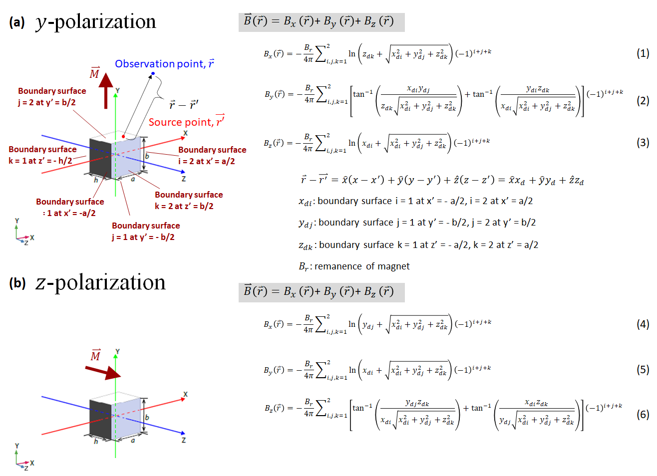
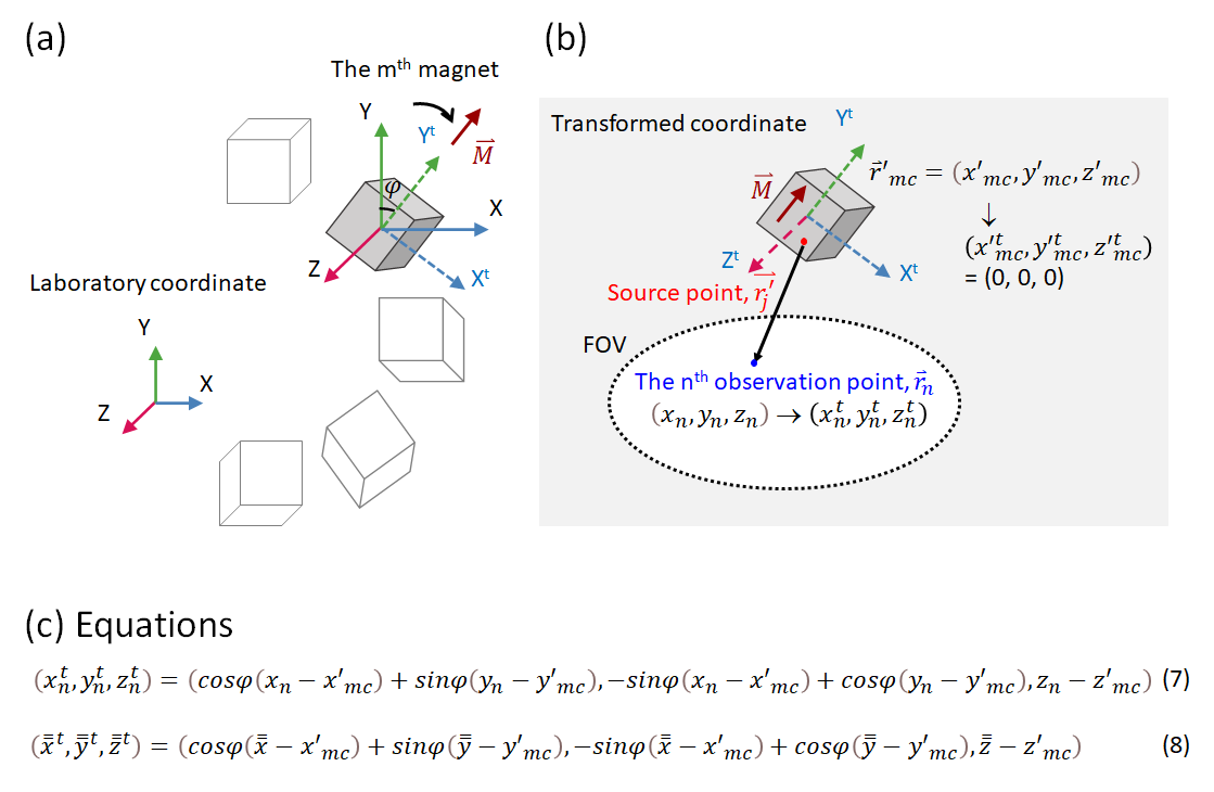
To calculate the magnetic field produced by a single magnet block, we use the current-based model which is summarized in Fig.1. Eq.(1)-(3) and (4)-(6) are the main equations to calculate the y- and z-polarized magnet blocks, respectively.The magnetic field at the nth observation point $$$\bar r_n$$$ at($$$x_n$$$,$$$y_n$$$,$$$z_n$$$) in the field of view produced by the mth magnet block centered at($$$x'_{mc}$$$,$$$y'_{mc}$$$,$$$z'_{mc}$$$) can be calculated based on Eq.(1)-(6) and the following transformation of coordinates with an illustration in Fig.2. A y-polarized magnet is taken as an example. In Fig.2(a), the highlighted magnet is a y-polarized one rotated with an angle of φ from the Y-axis of the laboratory coordinate XYZ-system. Therefore, when the coordinate system is transformed to have the origin at($$$x'_{mc}$$$,$$$y'_{mc}$$$,$$$z'_{mc}$$$) with the magnetization aligned with the transformed y-axis(Yt,rotated φ from the Y-axis)(the coordinates of the observation point$$$\bar r_n$$$=($$$x_n$$$,$$$y_n$$$,$$$z_n$$$) are transformed as shown by Eq.(7) in Fig. 2 to$$$\bar r^t_n$$$=($$$x^t_n$$$,$$$y^t_n$$$,$$$z^t_n$$$)), the magnetic field at point$$$\bar r_n$$$ can be calculated using Eq.(1)-(3) for a y-polarized magnet shown in Fig.1(a).
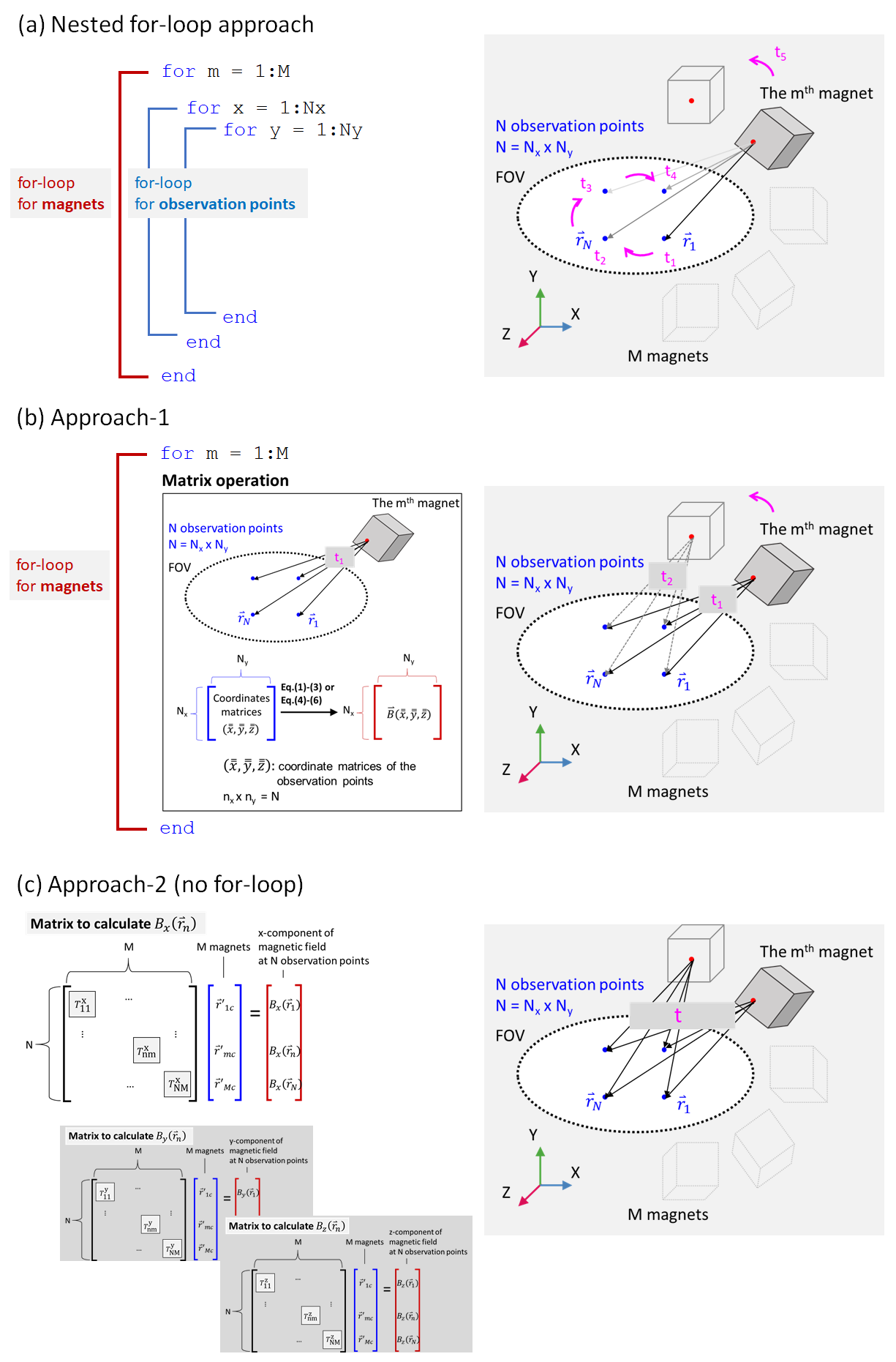
For calculation, the most intuitive approach is to loop over all the observation points in the field-of-view(FoV) and all the magnets(the nested for-loop approach) as shown in Fig.3(a). If there are M magnets and N observation points(N=Nx×Ny), then the complexity of the nested for-loops is O(M×Nx×Ny). For a magnet array that normally consists of more than 1000 pieces of magnets and a FoV that has more than 20,000observation points easily, the traditional approach is time-consuming. To accelerate the calculation, two approaches are proposed by exploiting Matlab matrix operations.
In Approach-1, rather than a one-to-one source point to observation point nested for-loop approach, all the N observation points in the FoV, $$$\bar r_i$$$(i=1,2,…,N) form matrices ($$$\bar{\bar x}$$$,$$$\bar{\bar y}$$$,$$$\bar{\bar z}$$$) (i.e. the coordinate matrices) which have the transformed ones as ($$$\bar{\bar x}^t$$$,$$$\bar{\bar y}^t$$$,$$$\bar{\bar z}^t$$$) (expressed in Eq.(8) in Fig.2). Substitute Eq.(8) into Eq.(1)-(6) in Fig.1, the magnetic fields of all the observation points generated by each magnet block can be calculated using a single matrix operation. Therefore, with the superposition principle, the total magnetic field of a whole magnet array can be calculated using a single for-loop for the magnets. This is illustrated in Fig.3(b).
Appoach-2 is shown in Fig.3(c). As shown by the formulation on the left, the size, grade, and polarization of the magnets are combined and arranged into an array(in blue), and Eq.(1)-(6) are re-arranged to enter the entry($$$T^{x/y/z}_{nm}$$$) of a calculation matrix(in black) encrypting the information on the relative location and orientation between the mth magnet and the nth observation point to calculate the x-, y-, or z-component of the magnetic field at the targeted observation point. The fields at all the observation points(the array in red) can be calculated through a single matrix-array-multiplication three times. Taking this approach, no for-loops are needed.
Results & Discussions
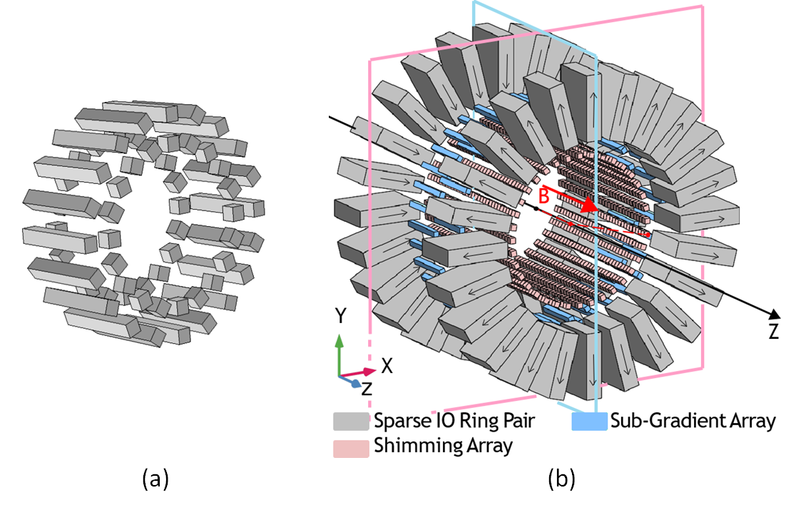
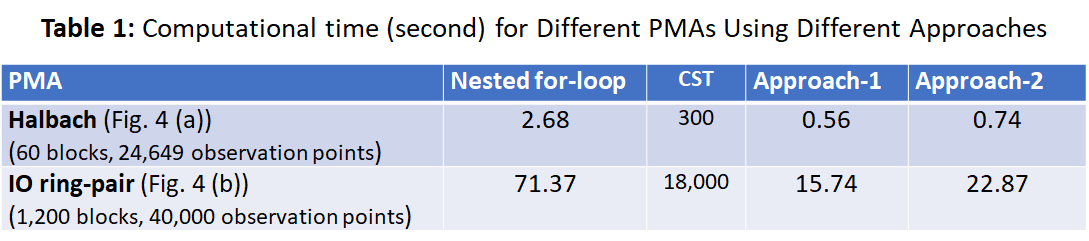
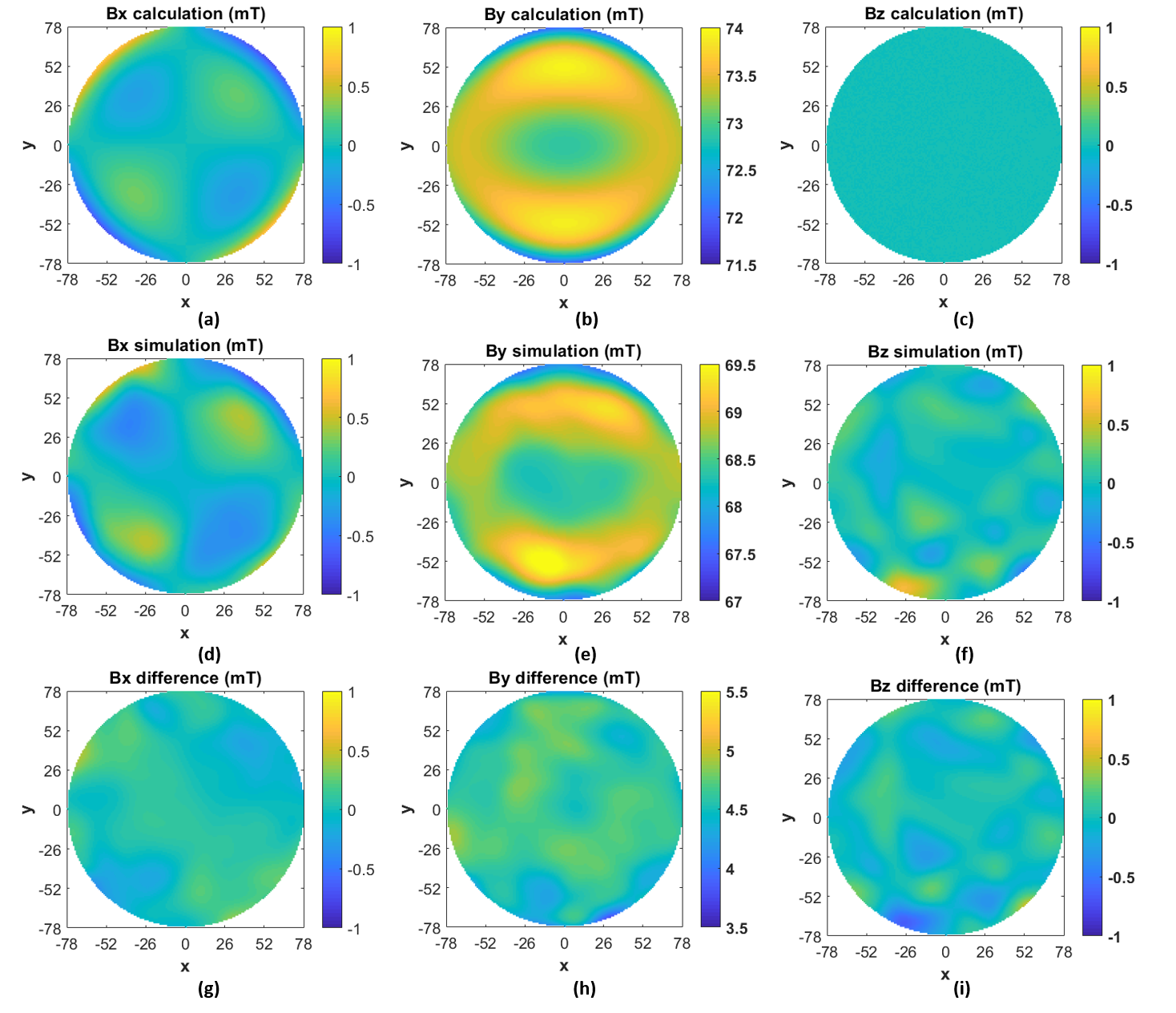
Fig.5 shows the computational times for the Halbach-array[6](Fig.4(a), 60blocks) and the sparse inward-outward(IO)-ring-pair-PMA[5](Fig.4(b), 1200blocks) using the two proposed approaches, and those using the nested for-loops and FEM. The processor of the computer is Intel(R)Core(TM)i7-8665U-CPU@1.9GHz-2.11GHz. For the Halbach, there are 24,649observation points in the FoV within a circle with a radius of 78mm at z=0mm whereas for the IO structure, there are 40,000points in the same FoV. As seen, Approach-1 has a time-reduction of 78.92% and 77.94% compared to the traditional approach for Halbach and IO-PMA, respectively. For Approach-2, the reduction is 72.32% and 67.96%, respectively. The time-reduction compared to FEM is >95%. It can clearly be seen that the proposed approaches have effectively and significantly reduced the computational time. This is crucial to the optimization of PMAs.The accuracy of the code is checked by comparing to the results obtained from the FEM-based software CST. The results for the Halbach-array are shown,(a)-(c)are the x-,y-,z-components of the calculated results using Approach-1, (d)-(f)are the corresponding ones using cst, and (g)-(i)shows the corresponding difference between the two. As shown, the discrepancies are kept within 7%. These discrepancies can be due to the limited boundary and the limited mesh-density of the FEM calculation.
Conclusion
Two calculation acceleration approaches are proposed to calculate magnetic fields of PMAs that consist of magnet blocks. They increase the calculation speed by about 70%. This will enable a speedy convergence of optimization of a PMA design that is a key component of a body-part-dedicated portable MRI system. These acceleration approaches can be extended to magnets of other shapes.Acknowledgements
No acknowledgement found.References
[1] S. Y. Huang, et al, " Portable Low-cost MRI System based on Permanent Magnets/Magnet Arrays", Investigative Magnetic Resonance Imaging, vol. 23, no. 3, page 179, Sept. 2019
[2] C. Z. Cooley et al, “A portable scanner for magnetic resonance imaging of the brain”, Nature Biomedical Engineering, Nov 2020
[3] T. O’Reilly et al, “In vivo 3D brain and extremity MRI at 50 mT using a permanent magnet Halbach array”, Magnetic resonance in medicine, June 2020
[4] C. Z. Cooley et al, “Design of Sparse Halbach Magnet Arrays for Portable MRI Using a Genetic Algorithm”, IEEE Transactions on Magnetics, VOL. 54, NO. 1, JANUARY 2018
[5] W. C. Mu, et al, Sparse Inward-outward (IO) Ring-Pair Permanent Magnet Array (PMA) with a Light Rotation Load for Low-field Head Portable MRI, Preprint, DOI: 10.13140/RG.2.2.23271.60320
[6] Z. H. Ren, et al, ‘Magnet Array for a Portable Magnetic Resonance Imaging System’, 2015 IEEE Microwave Theory and Techniques Society International Microwave Workshop Series on RF and Wireless Technologies for Biomedical and Healthcare Applications, Taipei, Taiwan, Sept. 2015
Figures