3100
Mechanical Tilt-Induced Gradient Fields for Low-Field Spokes-and-Hub Permanent Magnet MR Imagers
Irene Kuang1, Jason Stockmann2,3, Elfar Adalsteinsson1,4, and Jacob White1
1Electrical Engineering and Computer Science, Massachusetts Institute of Technology, Cambridge, MA, United States, 2A. A. Martinos Center for Biomedical Imaging, Massachusetts General Hospital, Charlestown, MA, United States, 3Harvard Medical School, Boston, MA, United States, 4Institute for Medical Engineering and Science, Massachusetts Institute of Technology, Cambridge, MA, United States
1Electrical Engineering and Computer Science, Massachusetts Institute of Technology, Cambridge, MA, United States, 2A. A. Martinos Center for Biomedical Imaging, Massachusetts General Hospital, Charlestown, MA, United States, 3Harvard Medical School, Boston, MA, United States, 4Institute for Medical Engineering and Science, Massachusetts Institute of Technology, Cambridge, MA, United States
Synopsis
As recently demonstrated by Cooley et al., for Halbach-array based permanent-magnet MR imagers, time-varying encoding fields can be generated mechanically, by rotating the entire array. In this paper we show that in spokes-and-hub based permanent magnet imagers, time-varying encoding fields can also be generated mechanically, but with much smaller motions. In particular, we show that a quarter-degree magnet tilt, along an easily precessed axis, can produce a spatially-discriminating field gradient. We demonstrate the spatial discrimation using both simulation and measurements from our recently-presented prototype imager.
Introduction
Permanent magnet MR research has accelerated in recent years due to the declining costs of rare earth permanent magnets and RF embedded systems hardware.1 We describe in this paper an approach for mechanically generating gradient fields in a spokes-and-hub magnet topology, building on previously reported design and optimization frameworks for these point-of-care and educational low-field MR systems.2,3,4Methods
The spokes-and-hub magnet topology shown in Fig. 1, an easily assembled magnet inspired by Aubert rings, consists of two densely-packed rings (“hubs”) of rectangular bar magnets (“spokes”). When optimally separated, the pair of spokes-and-hub magnets generate a radially symmetric field with exceptional center-plane uniformity.2,5-8 For the particular magnet presented in Figure 1, the center-point field is 191.7 mT, and center plane field uniformity is a few hundreds of ppm over an 8mm x 8mm desired imaging slice. Simulated fields using a calibrated equivalent-charge-based approach is shown in Fig. 2.Generalized projection-based image reconstruction methods have previously been presented for a Halbach magnet by Cooley et al. using rotation of the magnet’s explicitly-designed inhomogeneous field patterns as a substitute for switchable gradients.4,9,10 Here we employ a related approach for image encoding mechanical tilt of a more homogeneous spokes-and-hub magnet. Figure 3 illustrates the simulated B0 in the center slice of the magnet shown in Fig. 1 when a small 0.25° tilt is applied along the x-axis on one of the magnet hubs. The simulation shows that this change in magnet geometry results in departure from radially symmetric field patterns and the appearance of an approximately linear gradient field (29.4 mT/m) when moving along the tilt direction. Summing the B0 fields across an 8x8x8mm imaging volume, there is a clear broadening of the frequency spectrum when a tilt is applied compared to the narrow spectrum of the homogeneity-optimized un-tilted magnet as depicted in Fig 4(b).
Spin echoes were obtained on a single-channel, unshielded solenoid coil using a low-cost ultrasound pulser (STHV800) signal chain using dithered 90° and 180° RF pulses with 100kHz bandwidth generated by Teensy 4.0 microcontroller (Fig. 1).2
Results
Figure 4(c) shows the RF pulses spin echo signal obtained from the magnet when exciting an 8mm diameter test tube of water. The frequency spectrum of the spin echoes are shown in Fig. 4(d). Comparing the magnet with no tilt and a 0.25° tilt, there is a broadening of the spectrum as expected from the simulation in Fig. 4(b) when the mechanical tilt is applied as well as a narrowing of the time domain signal.Preliminary demonstration of the feasibility of projection-based encoding is shown in Fig. 5 using an 8mm diameter phantom containing two adjacent tubes of water. When the phantom tubes are placed horizontally along the z-directed B0 field, there are two distinct peaks in the frequency spectrum when a tilted gradient is applied in the direction of the tubes of water as seen in Fig. 5(a). Consequently when the phantom is rotated 90° in Fig. 5(b), there is no separation in the frequency spectrum as the phantoms are orthogonal to the applied gradient field.
Discussion
The simulations and corresponding measured data presented provides a proof-of-concept for imaging using a mechanically-generated gradient field with a spokes-and-hub magnet. The method avoids MR gradient coils (which in this case, would require driving 1.5 amps of current into a pair of 200 turn coils). Although there are slight mismatches in expected and measured frequency spectra, we suspect this can be strengthened through improved coil tuning/matching, RF pulse optimization, and mechanical design. A z-displacement of 0.2mm is required to obtain the 0.25° tilt angle for the magnet described in this work. To improve precision and gain refined control of the tilt mechanics, ongoing work is being done to utilize mechanical actuators such as piezoelectrics to generate a continuously precessing gradient field in multiple axes.Conclusion
We present a method for generating gradient field patterns that does not require external coils unlike traditional MR gradients using the flexible structure of the spokes-and-hub magnet topology. The hand-held sized magnet used here shows promise as an educational tool to teach projection-based encoding. Because there are no current or heating effect limitations, this permanent magnet and gradient approach can also be scaled up in size to be used for imaging in potential point-of-care applications.Acknowledgements
Funding support from NIH NIBIB R01EB018976, MIT-MGH seed grant, Skolkovo Institute of Science and Technology Next Generation Program, DoD NDSEG Fellowship, and MIT EECS department.References
- Wald LL, McDaniel PC, Witzel T, Stockmann JP, Cooley CZ. Low-Cost and Portable MRI. J. Magn. Reson. Imaging, 2019.
- Kuang I, Arango N, Stockmann J, Adalsteinsson E, White J. Equivalent-Charge-Based Optimization of Spokes-and-Hub Magnets for Hand-Held and Classroom MR Imaging. Proc. Intl. Soc. Mag. Reson. Med. 27., 2019.
- Kuang I, Arango N, Stockmann J, Adalsteinsson E, White J. Bloch-Optimized Dithered-Ultrasound-Pulse RF for Low-Field Inhomogeneous-Permanent-Magnet MR Imagers. Proc. Intl. Soc. Mag. Reson. Med. 28., 2020.
- Cooley CZ, Stockmann JP, Armstrong BD, Sarracanie M, Lev MH, Rosen MS, Wald LL. 2D Imaging in a Lightweight Portable MRI Scanner without Gradient Coils. Magn. Res. Med., 2015.
- Aubert G, Cylindrical permanent magnet with longitudinal induced field, US5014032A, 1991.
- Hugon C, D’Amico F, Aubert G, Sakellariou D. Design of arbitrarily homogeneous permanent magnet systems for NMR and MRI: theory and experimental developments of a simple portable magnet. J. Magn. Reson. Imaging, 2010.
- Ren ZH, Mu WC, Huang SY. Design and Optimization of a Ring-Pair Permanent Magnet Array for Head Imaging in a Low-Field Portable MRI System. IEEE Transactions on Magnetics, Vol. 55, 2019.
- Huang SY, Ren ZH, Obruchkov S, Gong J, Dykstra R, Yu W. Portable Low-Cost MRI System Based on Permanent Magnets/Magnet Arrays. iMRI, 2019.
- Cho ZH, Chung ST, Chung JY, Park SH, Kim JS, Moon CH, Hong IK. A new silent magnetic resonance imaging using a rotating DC gradient. Magn Reson Med., 1998.
- Schultz G, Gallichan D, Reisert M, Hennig J, Zaitsev M. MR image reconstruction from generalized projections. Magn Reson Med., 2013.
Figures
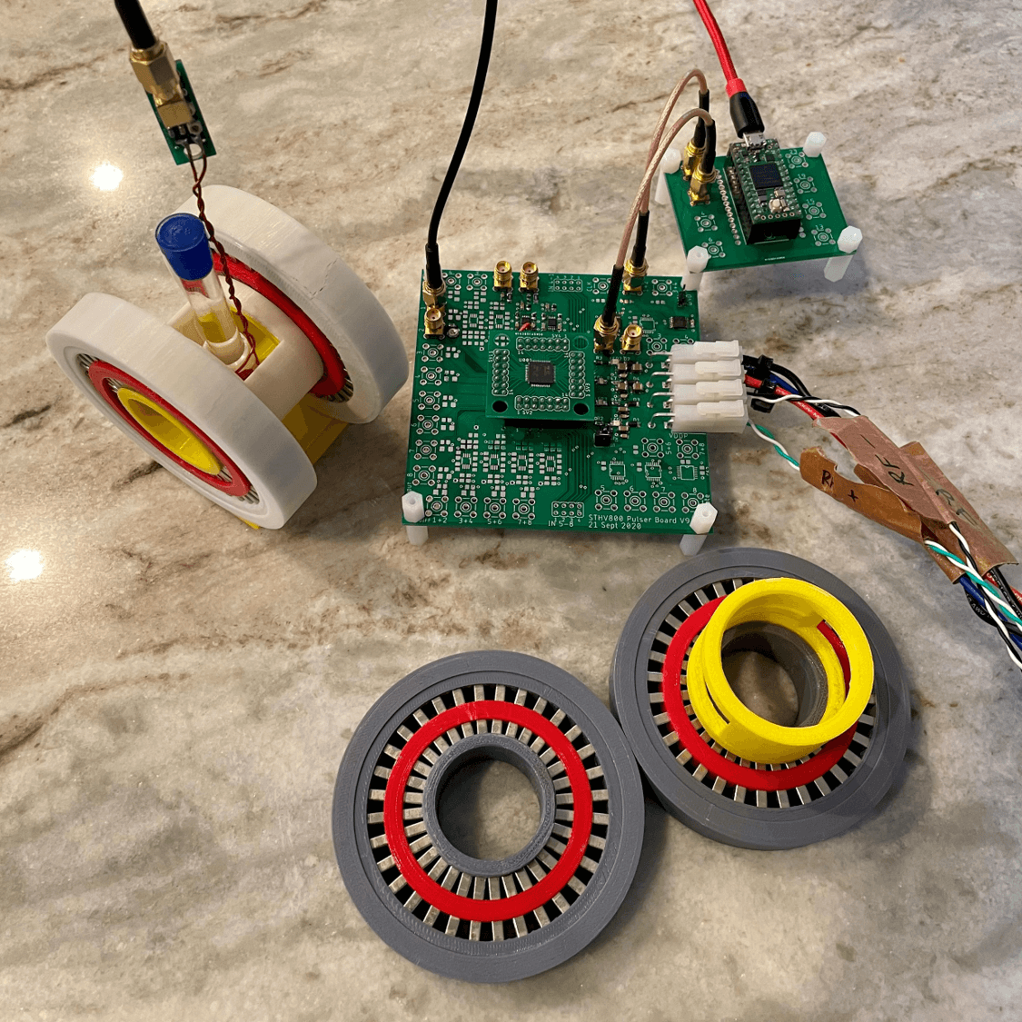
Figure 1. Spokes-and-hub magnet setup with STHV800 ultrasound pulser IC, Teensy 4.0 microcontroller, 8mm diameter test tube phantom, and unshielded coil. Disassembled magnet shown in lower right-hand corner.
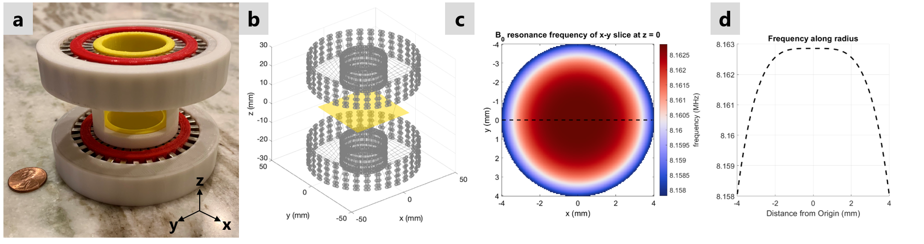
Figure 2. (a) Hand-held spokes-and-hub magnet with B0 = 191.7 mT, diameter = 17.2 mm; (b) Quadrature points for equivalent-charge based magnet simulation (gray), with center imaging plane at z = 0 shown in yellow; (c) Larmor frequency, in MHz, of the computed z-directed field for the circumscribed disk in the imaging plane; (d) Larmor frequency versus distance (e.g. along dotted line in (c)).
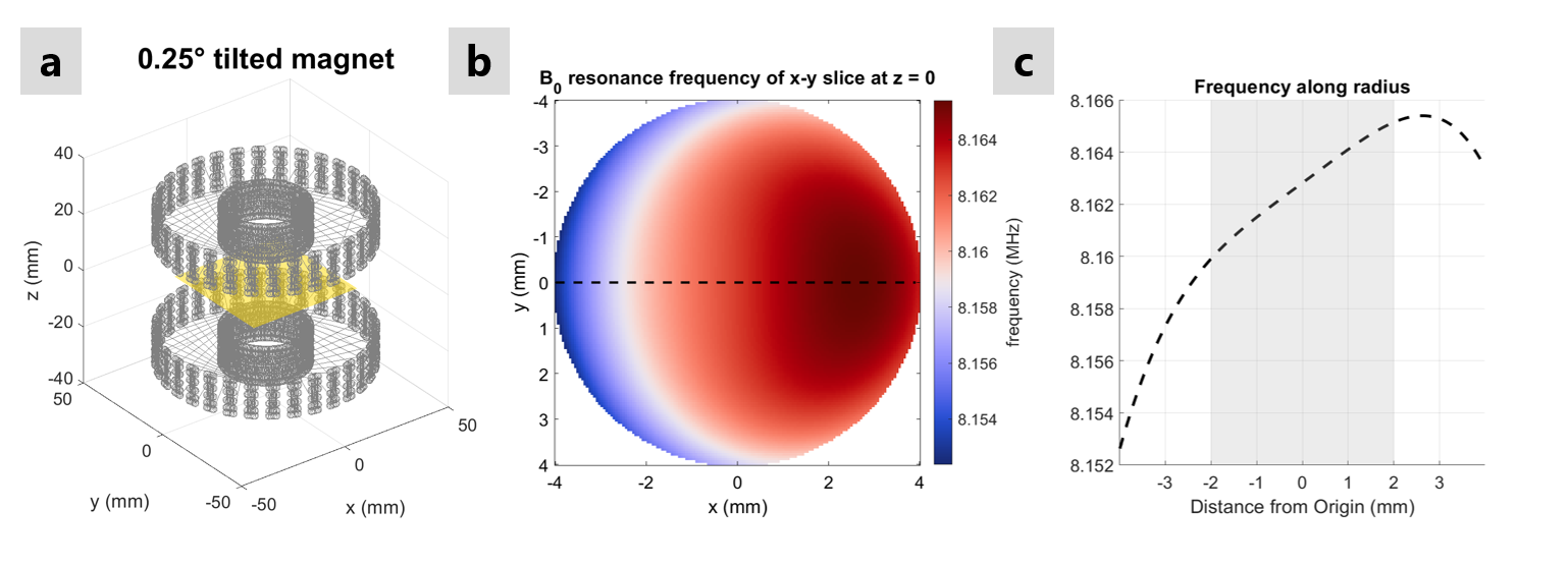
Figure 3. (a) Spokes-and-hub magnet with 0.25° tilt applied about the x-axis of one hub; (b) Simulated Larmor frequency of tilted magnet in MHz; (c) Frequency versus center distance (e.g. along dotted line in (b)) showing an approximately linear field (gray shaded region) over the range of x = -2 to 2 mm with gradient strength of 29.4 mT/m.
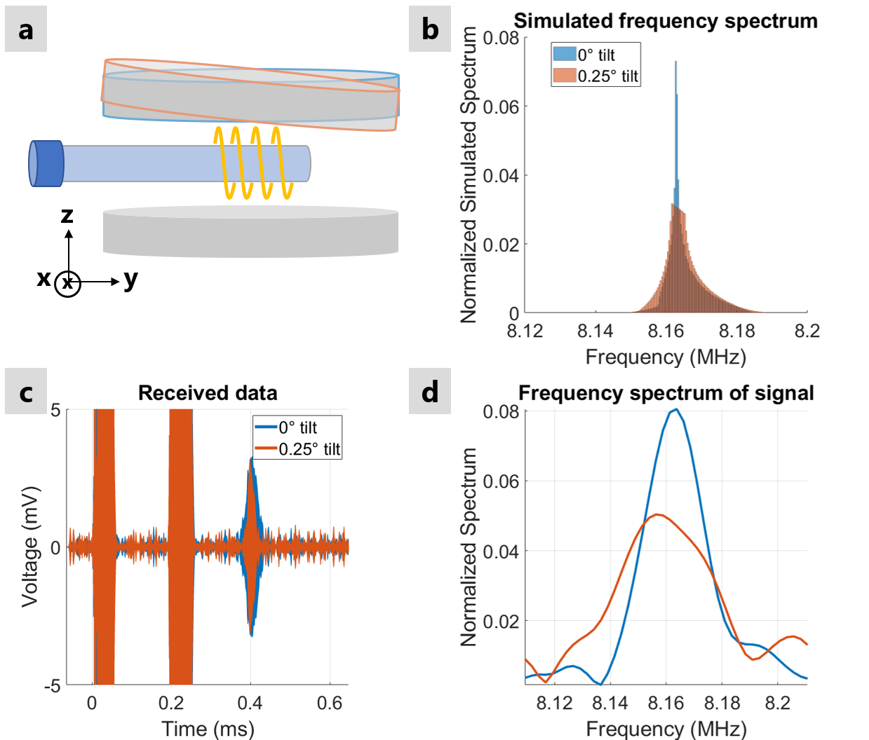
Figure 4. (a) Diagram of spokes-and-hub magnet with no tilt (blue outline) and a 0.25° tilt (orange outline) about the x-axis, creating a y-axis gradient field; (b) Simulated receive signal spectrum with and without tilt; (c) Measured spin echo obtained from 8mm diameter test tube of water using dithered ultrasound RF pulse with 100 kHz bandwidth with 0° (blue) and 0.25° (orange) tilted magnet; (d) Measured received signal spectrum with (orange) and without (blue) tilt.
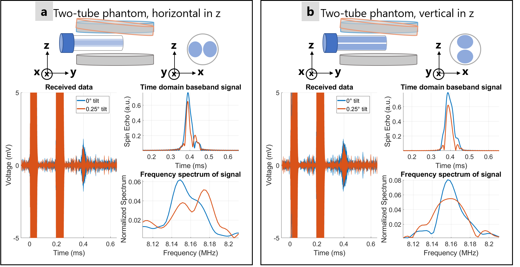
Figure 5. Repeat of experiment in Figure 4, but with an 8mm diameter phantom containing two distinct tubes of water. In (a), tubes are side-by-side (along the y axis and in line with the tilt-induced gradient field); and in (b), tubes are stacked (along the z axis, orthogonal to the gradient field). Note the clear double hump in (a) showing spatial separation.