3095
Gradient induced electric field within a shoulder cut-out gradient coil built for head and neck imaging.1xMR Labs, Physics and Astronomy, London, ON, Canada, 2Medical Biophysics, Western University, London, ON, Canada
Synopsis
This abstract aims to investigate the electromagnetic environment within a high-performance shoulder cut-out gradient coil designed to be used as a part of an all-in-one platform for head and neck imaging applications. The results achieved in this abstract and future measurements that will be performed with this coil will allow the quantification for gradient induced electric field effects experienced by patients and ensure that the coil is within the expected PNS limits.
Introduction
Head only MR scanners have the potential to provide improved imaging of the head compared to full body system generally used in hospitals. However, head only systems provide limited capabilities for neck imaging due to position of the neck and cervical spine outside of the main imaging region, as the patient is unable to slide their shoulders into the gradient coil. This abstract proposes the use of high-performance head and neck gradient coil achieved by adding cut-outs (length = 22.5 cm) to accommodate the patient’s shoulder. Investigation into the electromagnetic interactions experienced by a patient within such a coil is important as it will allow the quantification for gradient induced effects1,2 and will ensure that the coil is operating within the expected peripheral nerve stimulation (PNS) limits. As a part of this abstract, steps were taken to model the electric field within this coil in presence of an electrically conductive phantom mimicking the tissue environment.Method
Wire patterns for a shoulder cut-out head only gradient coil designed to fit within a bore of length 1.0 m and radius 0.3 m were exported from MATLAB for analysis. These patterns were designed using the boundary element method (BEM) as previously described.3 Although, these gradient coils were designed to produce linear field gradients along the diagonal as opposed to traditional x- and y-gradients, the wire patterns were rotated by pi/4 before exporting such that the linear variation is along the x- and y-axis for these simulations. The x and y axis coils were exported using an in-house MATLAB software, and then imported into Sim4Life (Zurich Med Tech.) to model the electromagnetic environment within the coils. As a part of this study, a cylindrical phantom (electrical conductivity = 0.47 S/m) with a length of 87 cm and a diameter of 50 cm was placed within these coils individually. This non anatomically correct phantom is a simple model and does not attempt to predict true PNS thresholds, as has been shown recently.4 Sinusoidal current with a peak amplitude of 1 A was applied through these coils at a frequency of 1 kHz. This operation frequency allowed the use of quasi-static approximations5 which led to the assumption of tissues being homogeneous, isotropic and uniform volume conductors. Simulations were performed using the low frequency magneto quasi-static solvers available in Sim4Life. Using Biot-Savart law in the quasi-static regime the vector potential within the coils were calculated. The solver then used the curl of the vector potentials in order to calculate the magnetic field. The electric field within the coils was calculated using tricubic interpolation. All boundary conditions were neglected as zero Neumann boundary conditions, i.e., vanishing normal flux. The tolerance for convergence had a relative value of 10-8.Results
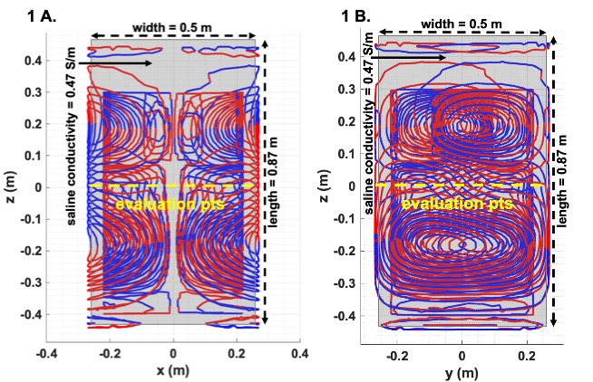
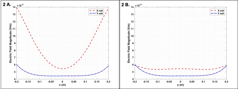
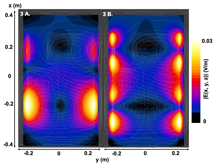
The x axis coil is shown in Figure 1 with evaluation points along the x and y axis at the isocenter of the coil. Figure 2 shows the simulated electric field along the line x = 0 and y = 0 on the xy plane at the isocenter for both the x and y coils, respectively. Figure 3 shows the simulated electric field on the yz plane at the center for the x and y axes coils.Discussion
Figure 2 shows the electric field variation within the x and y axes coils, with Figure 2a. and 2b. referring to the evaluation points given in Figure 1 respectively. The electric field discussed here is produced with 1A of current being driven across the coil. This figure suggests the x coil produces a higher electric field along the x axis. The magnitude of the electric field produced within the x coil along the y axis in the imaging region (a 0.2 m diameter sphere) is higher compared to the y coil. However, the difference between the fields is negligible near the edge of the coil. Figure 3 refers to the electric field behaviour on the yz plane at the center of the coil for both the x and y axes coils. This figure suggests, the effective electric field experienced by a patient within the imaging region (from approximately -0.1 m to 0.1 m) will primarily be produced by the y axis coil. It also shows that the electric field at the center is approximately 0.01 V/m while it increases to around 0.03 V/m near the edges.Conclusion
The high-performance head and neck gradient coil discussed in this abstract will be used as a part of an all-in-one platform for a host of head and neck imaging application. The electric field experienced by a patient within this coil is less than 0.03 V/m at 1A. However, the efficiency of the coils are approximately 0.13 mT/m/A. Due to this producing a gradient field of 80 mT/m would require a current of 615A with the resulting maximum electric field being approximately 18.45 V/m which is beyond the PNS threshold. It should be noted that such high gradient strengths would normally only be applied as diffusion pulses, which cause fewer PNS issues.Validation studies will be performed in future, with an ultra-low frequency electric field probe6,7 built to monitor gradient induced effects.Acknowledgements
The authors would like to thank the research and financial supports received from Natural Sciences and Engineering Research Council (NSERC) of Canada and the Ontario Research Fund (ORF).References
1. International Organization for Standarization. Assessment of the safety of magnetic resonance imaging for patients with an active implantable medical device. ISO/TS 10974. 2018;4.
2. Xin X, Chen XL, Sison S. A MRI Gradient Induced Electric Field Exposure System for Active Implanted Medical Devices. ISMRM. 2019; Abstract # 1440.
3. Lessard EJ et al. Proc. Intl. Soc. Mag. Reason. Med. 28 (2020) Abstract # 4247.
4. Mathias D. et al. Predicting Magnetostimulation Thresholds in Peripheral Nervous System using Realistic Body Models. Nature. 2017; 7:5316.
5. Roth BJ, Cohen LG, Hallett M. The Electric Field Induced During Magnetic Stimulation. Magn Mot Stimul Basic Princ Clin Exp. 1991;43:268-278.
6. Halder, A., Attaran, A., Handler, W. B., & Chronik, B. A. (2020). Electric Field Probe Used for Gradient Coil-Induced Field Measurements during Medical Device Testing: Design, Calibration, and Validation. IEEE Transactions on Antennas and Propagation, 68(5).
7. Glover PM, Bowtell R. Measurement of Electric Fields Due to Time-Varying Magnetic Field Gradients Using Dipole Probes. Physics in Medicine and Biology. 2007;52: 5119-5130.
Figures