3093
Droop compensation of gradient current waveforms in gradient array systems1Department of Electrical and Electronics Engineering, Bilkent University, Ankara, Turkey, 2National Magnetic Resonance Research Center (UMRAM), Ankara, Turkey
Synopsis
Providing accurate gradient currents is challenging due to the nonlinearity of the gradient system arising from gradient power amplifiers and power supply stages which causes droop in the output currents. This work introduces a nonlinear model for the gradient array system by using the state-space averaging technique and the nonlinear inversion of the model compensates for droop. The feasibility of the method is depicted by simulation and experimental results. The proposed method can provide desired currents by lower voltages which results in minimizing the needed power. It is also possible to use small capacitors to lower the cost of system.
Introduction
Recently introduced gradient array systems are capable of generating dynamically controllable gradient fields1-6. Driving multiple gradient coils needs independent gradient power amplifiers (GPAs) and power supplies. Providing accurate gradient currents is challenging due to GPAs and power supply imperfections. The large bulk capacitors are provided for each channel to supply most of the amplifiers’ switching current. However, the capacitor’s discharge causes a current droop. This effect is more pronounced for EPI applications, which demand high magnetic field strength and long pulses. Considering a linear first-order model for gradient system2,5,7 cannot address these issues. Therefore, to import the GPAs and also power supply stages in the general gradient system model, it can be treated as a switching converter, and the State Space Averaging technique8 can be applied to characterize the system. This work represents the gradient array system with a nonlinear second-order model and utilizing the inverse of the acquired model to regulate the gradient currents in the feed-forward open-loop configuration.Methods
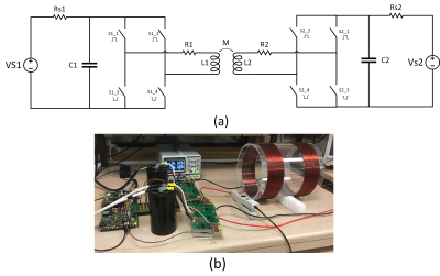
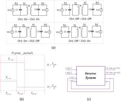
The gradient array system’s circuit diagram with two channels, including GPAs and power supply stages, is shown in Fig.1. The method of State-Space Averaging was developed to characterize the transfer properties of switching converter power stages. The dc-to-dc conversion function of the power amplifier is achieved by repetitive switching between linear networks consisting of lossless storage elements, inductances, and capacitances. On the assumption that the circuit operates in the continuous conduction mode in which the inductor currents do not change suddenly at any time in the cycle, there are only three different "states" of the circuit. Each state, however, can be represented by a corresponding set of state-space equations. Assuming $$${{D}_{1}}>{{D}_{2}}$$$ ($$${{D}_{1}}$$$: channel_1 duty cycle,$$${{D}_{2}}$$$: channel_2 duty cycle), during the intervals $$${{T}_{on-on}},{{T}_{on-off}},{{T}_{off-off}}$$$ (Fig.2.b), the system can be described by a set of linear, time-invariant differential equations:$${{T}_{on-on}}:{{\dot{x}}_{1}}(t)={{A}_{on-on}}{{x}_{1}}(t)+{{B}_{on-on}}{{V}_{s}}$$
$${{T}_{on-off}}:{{\dot{x}}_{2}}(t)={{A}_{on-off}}{{x}_{2}}(t)+{{B}_{on-off}}{{V}_{s}}$$
$${{T}_{off-off}}:{{\dot{x}}_{3}}(t)={{A}_{off-off}}{{x}_{3}}(t)+{{B}_{off-off}}{{V}_{s}}$$
Under the rapid switching assumption, the circuit’s general behaviour can be described as a single differential equation, which can be obtained as the above equation’s weighted average. The averaged state-space description (over a single period T) is:
$$\dot{x}(T)={{D}_{2}}(T){{\dot{x}}_{1}}+\left[ {{D}_{1}}(T)-{{D}_{2}}(T) \right]{{\dot{x}}_{2}}+\left[1-{{D}_{1}}(T)\right]{{\dot{x}}_{3}}$$
$$\dot{x}(T)=A(T)x(T)+B{{V}_{s}} (1)$$
where, $$$x(T)={{\left[ \begin{matrix}{{i}_{L1}}&{{v}_{C1}}&{{i}_{L2}}&{{v}_{C2}}\\\end{matrix} \right]}^{T}}$$$, $$${{V}_{s}}={{\left[\begin{matrix}{{V}_{s1}}&{{V}_{s2}}\\\end{matrix}\right]}^{T}}$$$
$$A(T)=\left[\begin{matrix}-\frac{{{R}_{1}}{{L}_{2}}}{{{L}_{1}}{{L}_{2}}-{{M}^{2}}}&\frac{{{L}_{2}}}{{{L}_{1}}{{L}_{2}}-{{M}^{2}}}{{D}_{1}}(T)&\frac{M{{R}_{2}}}{{{L}_{1}}{{L}_{2}}-{{M}^{2}}}&-\frac{M}{{{L}_{1}}{{L}_{2}}-{{M}^{2}}}{{D}_{2}}(T)\\-\frac{1}{{{C}_{1}}}{{D}_{1}}(T)&-\frac{1}{{{R}_{s1}}{{C}_{1}}}&0&0\\\frac{M{{R}_{1}}}{{{L}_{1}}{{L}_{2}}-{{M}^{2}}}&-\frac{M}{{{L}_{1}}{{L}_{2}}-{{M}^{2}}}{{D}_{1}}(T)&-\frac{{{R}_{2}}{{L}_{1}}}{{{L}_{1}}{{L}_{2}}-{{M}^{2}}}&\frac{{{L}_{1}}}{{{L}_{1}}{{L}_{2}}-{{M}^{2}}}{{D}_{2}}(T)\\0&0&-\frac{1}{{{C}_{2}}}{{D}_{2}}(T)&-\frac{1}{{{R}_{s2}}{{C}_{2}}}\\\end{matrix}\right],B=\left[\begin{matrix}0&0\\\frac{1}{{{R}_{s1}}{{C}_{1}}}&0\\0&0\\0&\frac{1}{{{R}_{s2}}{{C}_{2}}}\\\end{matrix}\right]$$
Equation (1) describes the gradient coil currents’ behaviour over a single period by considering the duty cycles as its inputs. Appearing the inputs inside the state matrix shows the nonlinear nature of the gradient system. To extract the required duty cycles for a set of desired currents, the equation (1) should be inverted.
The inverse system’s inputs are the reference gradient currents, and the outputs are the duty cycles that have to be applied to the GPAs (Fig2.c). We obtained a numerical algorithm by converting the differential equations into difference equations, and then, the duty cycles and reference voltages (capacitor voltages) are formulated as follow:
$${{D}_{1}}(n)=\frac{\frac{{{L}_{1}}}{T}\left[{{i}_{L1}}(n+1)-{{i}_{L1}}(n)\right]+{{R}_{1}}{{i}_{L1}}(n)+\frac{M}{T}\left[{{i}_{L2}}(n+1)-{{i}_{L2}}(n)\right]}{{{v}_{C1}}(n)}$$
$${{D}_{2}}(n)=\frac{\frac{{{L}_{2}}}{T}\left[{{i}_{L2}}(n+1)-{{i}_{L2}}(n)\right]+{{R}_{2}}{{i}_{L2}}(n)+\frac{M}{T}\left[{{i}_{L1}}(n+1)-{{i}_{L1}}(n)\right]}{{{v}_{C2}}(n)}$$
$${{v}_{C1}}(n+1)=\left(1-\frac{T}{{{R}_{s1}}{{C}_{1}}}\right){{v}_{C1}}(n)-\frac{T}{{{C}_{1}}}{{D}_{1}}(n){{i}_{L1}}(n)+\frac{T}{{{R}_{s1}}{{C}_{1}}}{{V}_{s1}}$$
$${{v}_{C2}}(n+1)=\left(1-\frac{T}{{{R}_{s2}}{{C}_{2}}}\right){{v}_{C2}}(n)-\frac{T}{{{C}_{2}}}{{D}_{2}}(n){{i}_{L2}}(n)+\frac{T}{{{R}_{s2}}{{C}_{2}}}{{V}_{s2}}$$
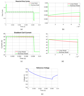
$$${{D}_{1}}(n),{{D}_{2}}(n)$$$ are the nth PWM period’s duty cycles. In the linear model, the reference voltages are considered as a constant, however, due to the capacitors discharge they will not be the same for all the cycles. The nonlinear model uses the actual value of reference voltages, which changes cycle to cycle, to calculate the duty cycles.
Results
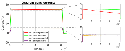
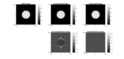
Considering a trapezoidal current waveform as a reference input, the required duty cycle for a single channel is shown in Fig.3(a) for the linear and nonlinear models. When the two models are compared, it can be visualized that the nonlinear model compensates for the current errors due to the voltage droop, as shown in Fig.3(c). The experiment results also are in good agreement with the simulation results (Fig.4). We used 150V/50A for channel-1 and 150V/10A for channel-2. Both channels’ inductances are similar (410μH), and the mutual inductance is 48μH. The decoupling capacitors’ value is the same for both channels (5.6mF). The image simulations (Fig.5) for compensated and uncompensated waveforms used in the x gradient direction show the proposed method’s effectiveness.Discussion and Conclusion
In this work, we presented a nonlinear model to describe the gradient array systems. The digitally inverted model was used to control the gradient current waveforms in an open-loop configuration. The effect of voltage droop in the output currents is more noticeable if we want to reach high currents with low supply voltages (applicable for low inductance coils in the array systems). Our proposed method can provide the desired currents by lower voltages which results in minimizing the needed power. Other advantages of the proposed method are, for example, using low value (small) capacitors to lower the cost of the system without compromising the quality of the output. It can also decrease the load of the feedback loop in the case of using a closed-loop configuration.Acknowledgements
No acknowledgement found.References
1. Ertan, K., Taraghinia, S., Sadeghi, A. and Atalar, E. (2018), “A z‐gradient array for simultaneous multi-slice excitation with a single‐band RF pulse,” Magn. Reson. Med, 80: 400-412.
2. Ertan, K, Taraghinia, S, Atalar, E. “Driving mutually coupled gradient array coils in magnetic resonance imaging,” Magn Reson Med. 2019; 82: 1187– 1198.
3. Smith E, Freschi F, Repetto M, Crozier S. “The coil array method for creating a dynamic imaging volume”, Magn Reson Med. 2017; 78: 784– 793.
4. Littin S, Jia F, Layton KJ, et al. “Development and implementation of an 84‐channel matrix gradient coil,” Magnetic resonance in medicine. 2018 Feb;79(2):1181-91.
5. Babaloo, R., Taraghinia, S. Acikel, V., Takrimi, M., and Atalar, E. “Digital Feedback Design for Mutual Coupling Compensation in Gradient Array System,” Proceedings of the 28th Annual Meeting of ISMRM, 2020.
6. Takrimi, M. and Atalar, E., “A Programmable Set of Z-Gradient Array and Active-Shield Array for Magnetic Resonance Imaging”, Proceedings of the 28th Annual Meeting of ISMRM, 2020.
7. Sabaté, Juan A., et al. “Magnetic resonance imaging power: High-performance MVA gradient drivers.,” IEEE Journal of Emerging and Selected Topics in Power Electronics 4.1 (2015): 280-292.
8. Middlebrook, R.D., Cuk, S., “A general unified approach to modelling switching-converter power stages,” IEEE Power Electronics Specialists Conference, 1976.
Figures
