3092
Design and Implementation of High Switching Frequency Gradient Power Amplifier Using eGaN Devices1UMRAM, Bilkent University, Ankara, Turkey, 2Aselsan A.S., Ankara, Turkey, 3Electrical and Electronics Engineering, Bilkent University, Ankara, Turkey
Synopsis
In this work, a switching H-bridge gradient power amplifier utilizing eGaN devices is implemented. A single-stage 150 V/ 50 A full-bridge GPA for an insert gradient array system at 1 MHz effective switching frequency is fabricated and tested. Pulse width modulation signals are generated digitally using a Virtex 7 family FPGA board. A single-stage LC low pass filter is designed to attenuate the ripple current.
Introduction
Switching H-bridge gradient power amplifiers (GPAs) are the most popular systems in the MRI scanners1. The MR image quality highly depends on the fidelity of the output current. The pulse width modulation (PWM) switching frequency in a conventional GPA is about 100 kHz. This is achieved by interleaving multiple amplifier stages with IGBT modules or using new generation silicon carbide (SiC) switching devices and fewer power stages2,3. The attenuation of ripple currents and switching noises is necessary to prevent image quality degradation. Using multiple stages of LC low pass filters, coupled-inductor-based ripple cancellation4, and optimum-phase PWM5,6 signals are the most common methods to attenuate ripple currents.Recently developed gradient arrays7,8,9,10 and high order active shimming systems11 draw attention due to their flexibility and promising applications. In this work, a single-stage gradient amplifier prototype with 150 V/ 50 A voltage and current ratings and 1 MHz effective PWM frequency is put into practice by utilizing new generation e-mode gallium nitride (eGaN) power transistors. A single-stage LC low pass filter to attenuate the 1 MHz ripple current is designed and implemented.
Methods
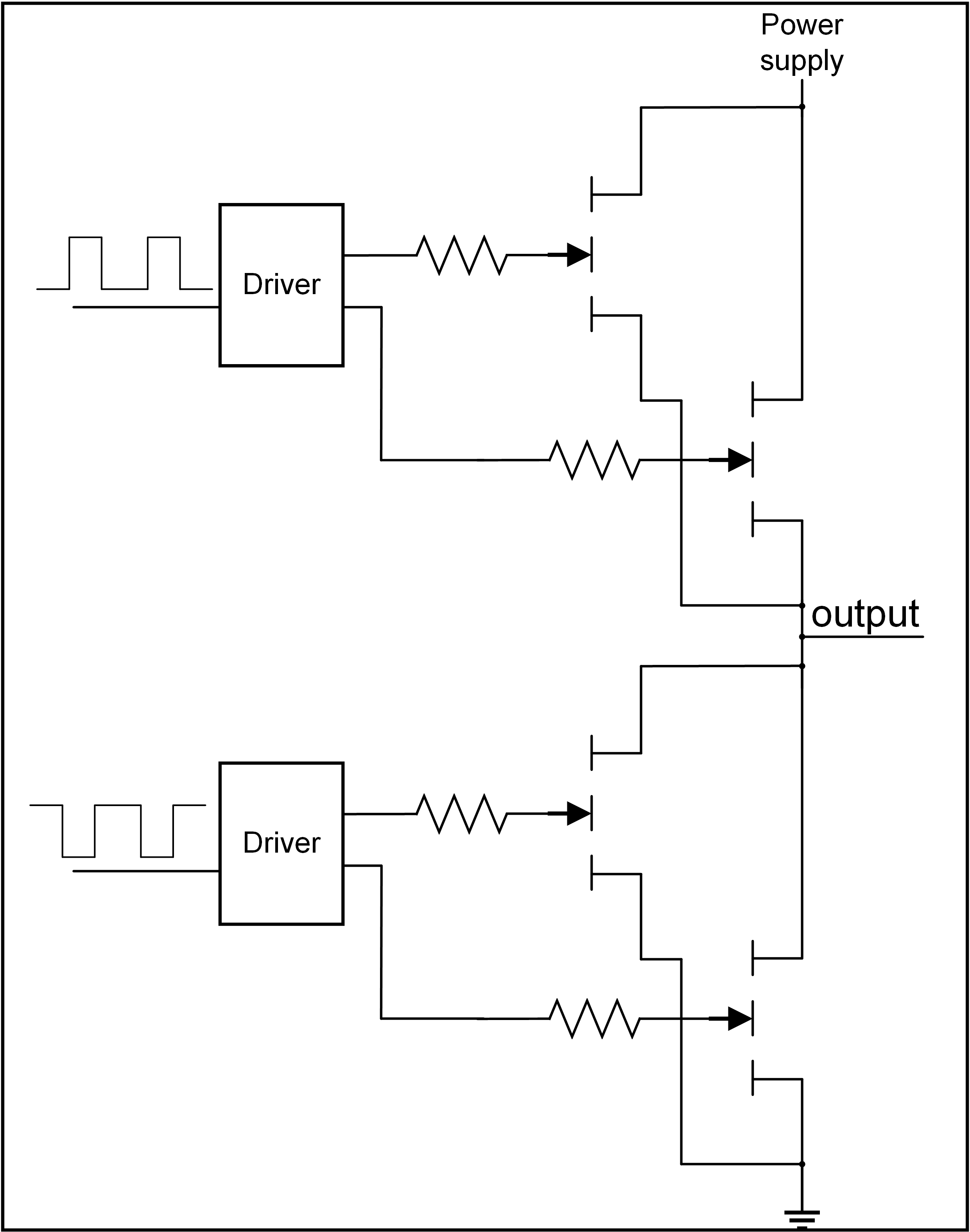
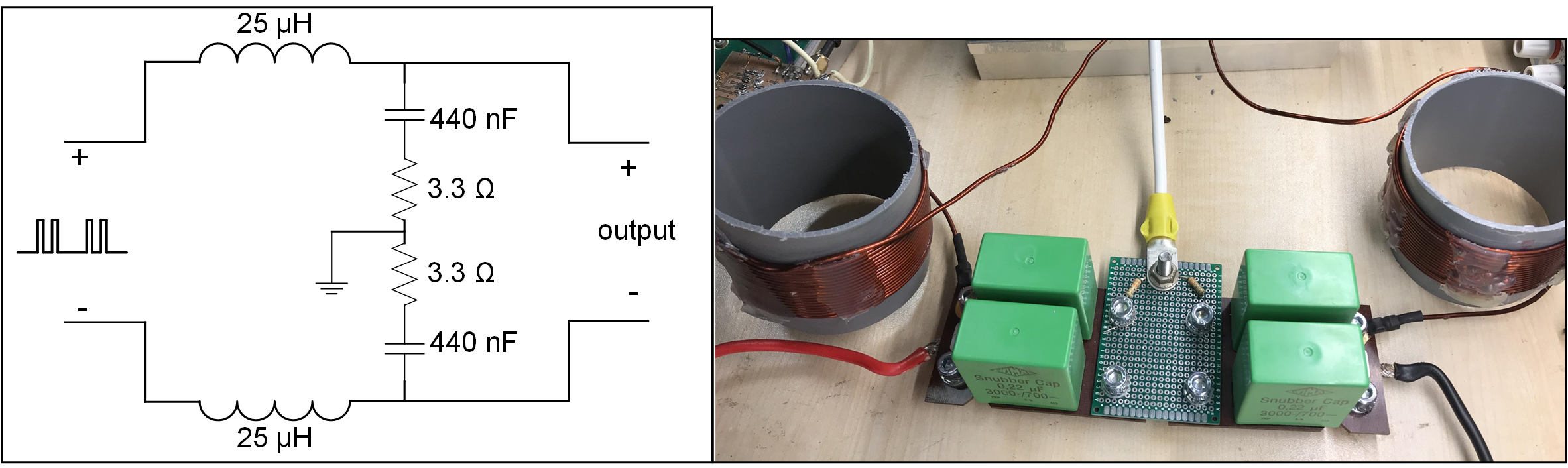
By the introduction of SiC and eGaN transistors, conventional designs, implementing IGBT or Si modules can be upgraded accordingly. Compared to SiC devices, eGaN transistors have the advantage of 3-5 times higher electron mobility12. The eGaN transistors can operate in high-voltage, high-temperature, and high-frequency reliability. Furthermore, a gradient array’s power requirement is significantly less for each channel compared to conventional systems13. Therefore, we fabricated a 150 V/ 50 A one-stage full-bridge GPA for an insert gradient array system utilizing two parallel eGaN for high- and low-sides separately (Fig. 1). A center-aligned 500 kHz PWM signal is used that results in a 1 MHz effective PWM frequency. Floating supplies are designed for both high- and low-sides to supply gate-driver ICs. Deadtime between high side and low side switches are implemented to prevent shoot-through. A Virtex 7 family (VC707) evaluation board is used to generate high-resolution PWM pulses14. The half-bridge module is placed on a heat sink, which is air-cooled.The size of passive components, the amount of phase shift introduced to the control loop, the inductance value used in the filter compared to the inductance of the load, and simplicity are the essential filter design parameters. Fig. 2 depicts a single-stage differential LC filter used at the output of the H-bridge driver. Since the ripple current frequency is at 1 MHz, the filter’s cut-off frequency is adjusted to about 50 kHz, allowing high bandwidth for gradient amplifier and sufficient ripple current attenuation.
Results
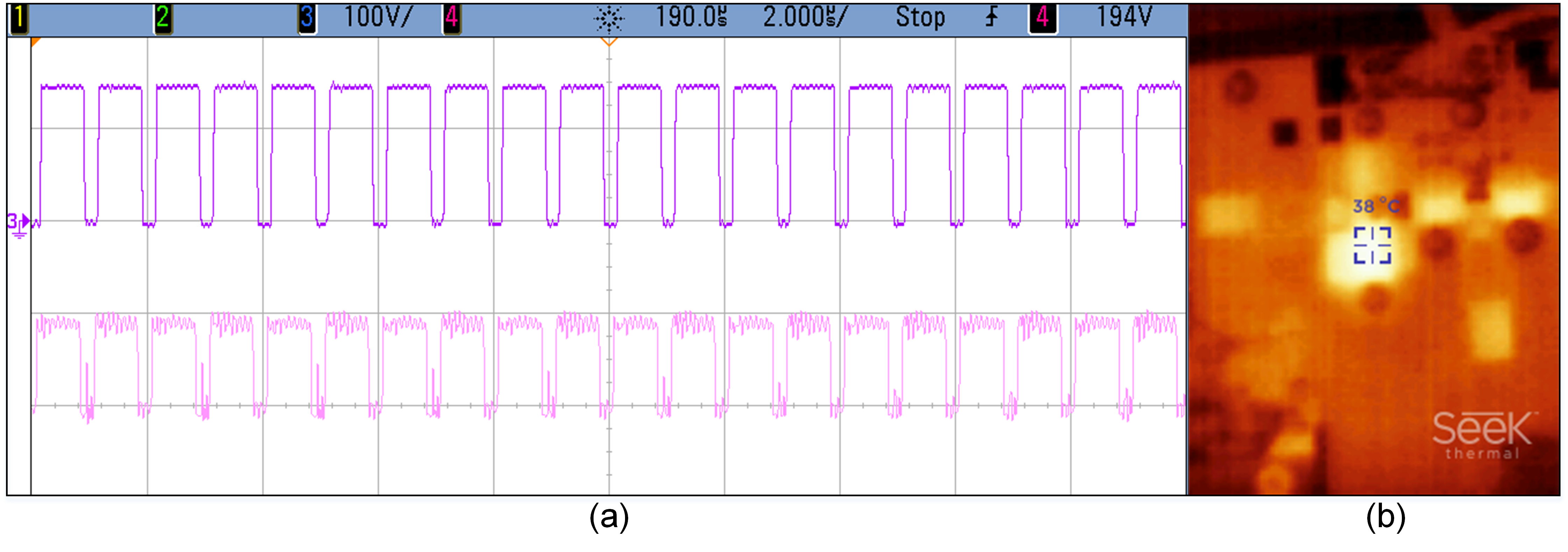
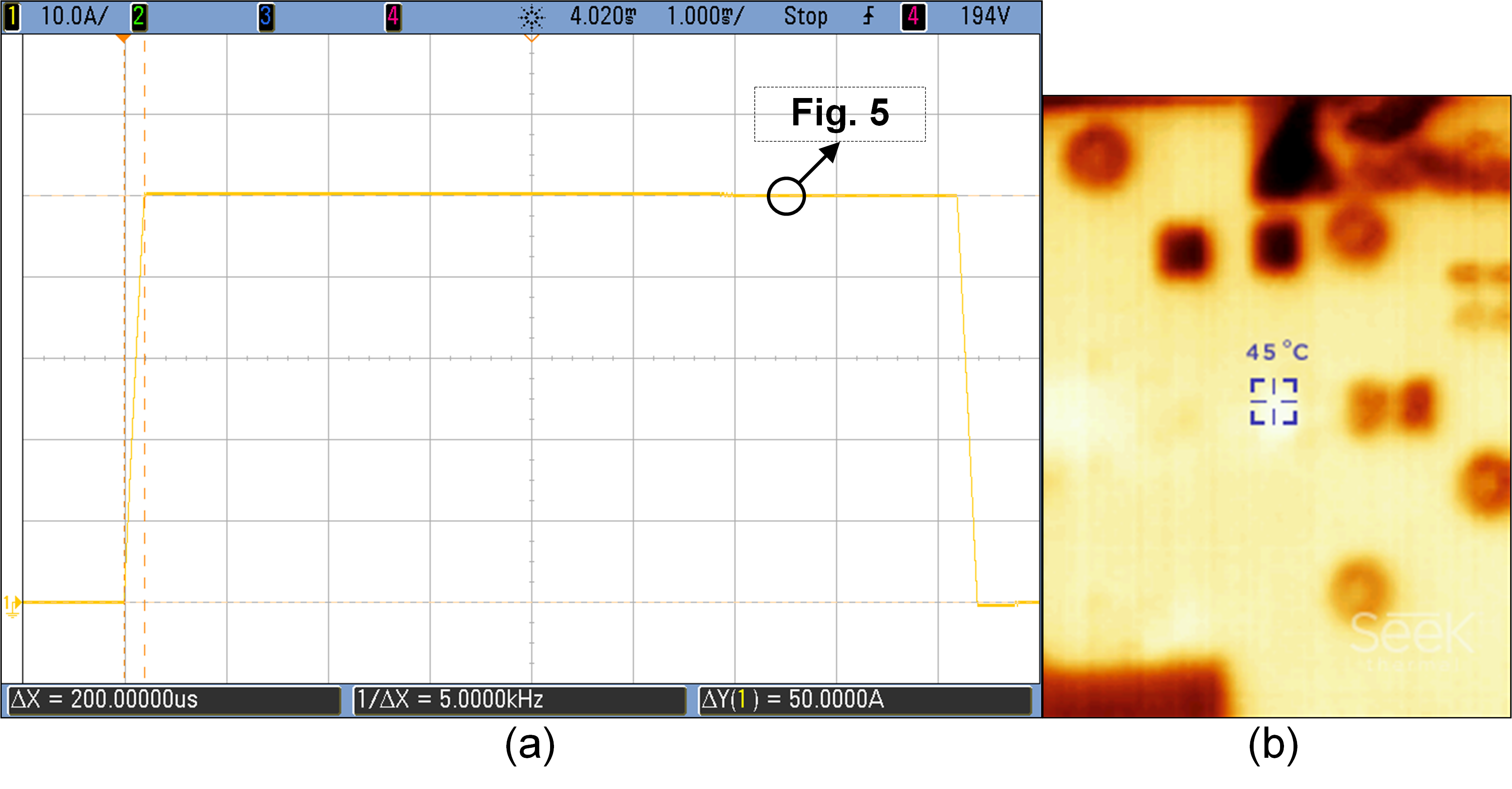
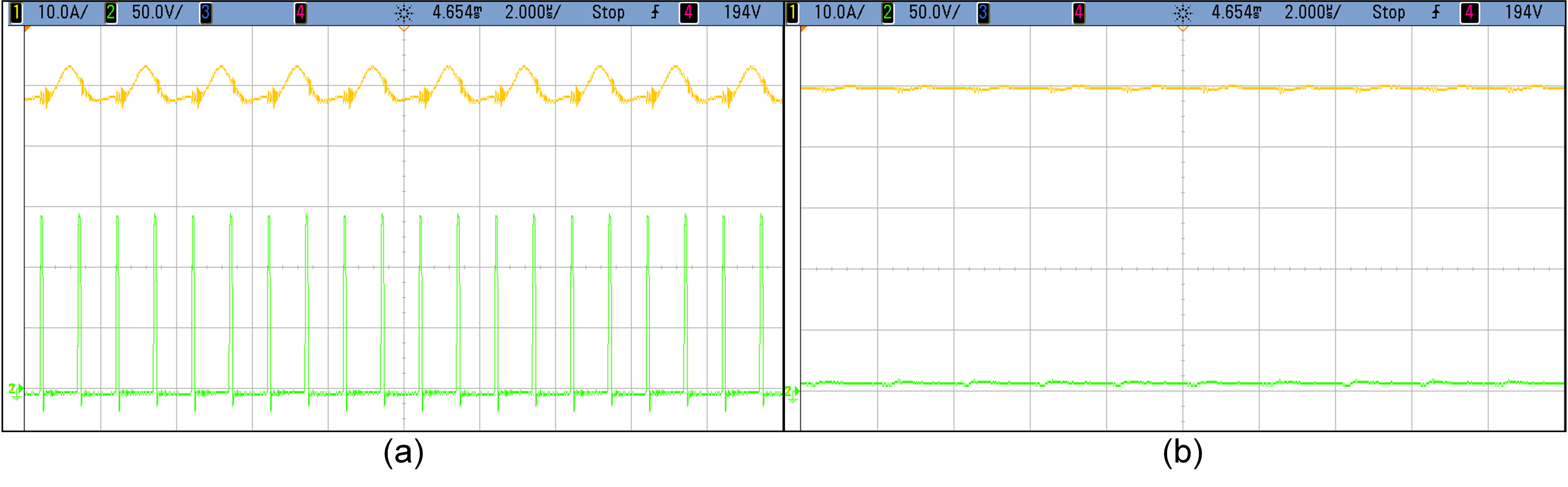
Fig. 3a shows the measured control PWM signals and switched 150 V pulses at the H-bridge amplifier’s output without load and LC filter at 1 MHz effective frequency. In Fig. 3b, the thermal camera capture exhibits the transistors’ temperature, indicating that the high switching did not reduce efficiency. Fig. 4a depicts a trapezoidal current waveform flowing in a 410 µH coil with 50 A flat-top current and 200 µs rise/fall time with filter. Temperature increase for five minutes of operation with a 10% duty cycle is shown in Fig. 4b, indicating good thermal conductivity. Fig. 5 shows a zoomed version of the current and voltage waveform in Fig. 4 applied to the coil with and without an LC filter. Good ripple current attenuation and minimum gradient current distortion are achieved.Discussion and Conclusion
In this work, the feasibility of using eGaN transistors for high switching frequency H-bridge current driver for gradient array applications was shown. Cascade and parallel configurations can be utilized in order to deliver higher current and voltage with high effective PWM frequencies. Although the fabricated H-bridge modules are designed to be capable of 400 V/ 100 A operation ratings, smaller ratings were tested to be on the safe side. Ripple currents with high frequencies resulted in moderate filter requirements. The voltage needed to achieve the desired slew rate is reduced due to smaller inductance values in the filter. The capacitors’ self-resonance frequency must be high enough to maintain the filter’s effectiveness at switching frequencies. Since the closed-loop control system was not utilized in this configuration, the filter’s effect on the control loop was not evaluated, and it will be considered future work.Acknowledgements
No acknowledgement found.References
[1] Robert L. Steigerwald, William F. Wirth, “High-Power, HighPerformance Switching Amplifier Driving Magnetic Resonance Imaging Gradient Coils,” IEEE PESC 2000 Conf. Records, pp.643-647.
[2] Sabaté, Juan A., et al. "Magnetic resonance imaging power: High-performance MVA gradient drivers." IEEE Journal of Emerging and Selected Topics in Power Electronics 4.1 (2015): 280-292.
[3] Ruxi Wang1, Juan Sabate1, Viswanathan Kanakasabai2, Yash Singh3, Jayanti Ganesh2, and Huan Hu3 Advanced Gradient Driver Design with Silicon Carbide MOSFETs ISMRM conference 2018 Paris, France
[4] Sabate J, Schutten M, Steigerwald R, et al. Ripple cancellation filter for magnetic resonance imaging gradient amplifiers. IEEE APEC’04, 2004: 792-796.
[5] Taraghinia, S., Ertan, K., Yardim, A.B. and Atalar, E., Efficient Ripple Current Reduction in Gradient Array System Using Optimized Phase Control Signals with One Stage LC Filter, ESMRMB 2017, Barcelona, Spain.
[6] Taraghinia, S., Ertan, K. and Atalar, E., Minimum Current Ripple in the Gradient Array System by Applying Optimum-Phase Pulse-Width Modulation Pattern, ISMRM 2017, Honolulu, Hawaii.
[7] Ertan K., Taraghinia, S., Sadeghi A., Atalar E., A Z-Gradient Array for Simultaneous Multi-Slice Excitation with a Single Band RF pulse. Magnetic Resonance in Medicine 2018; 80: 400-412
[8] Ertan, K., Taraghinia, S. and Atalar, E., Dynamic Optimization of Gradient Field Performance Using a Z-Gradient Array, ISMRM, Montreal, Canada, 2019
[9] Littin, Sebastian, et al. "Development and implementation of an 84‐channel matrix gradient coil." Magnetic resonance in medicine 79.2 (2018): 1181-1191.
[10] Takrimi, M. and Atalar, E., A Programmable Set of Z-Gradient Array and Active-Shield Array for Magnetic Resonance Imaging, ISMRM, Virtual, 2020
[11] Juchem, Christoph, et al. "Dynamic multi-coil technique (DYNAMITE) shimming for echo-planar imaging of the human brain at 7 Tesla." Neuroimage 105 (2015): 462-472.
[12] Pengelly, Raymond S., et al. "A review of GaN on SiC high electron-mobility power transistors and MMICs." IEEE Transactions on Microwave Theory and Techniques 60.6 (2012): 1764-1783.
[13] Ertan K., Taraghinia, S., Atalar E., Driving Mutually Coupled Gradient Array Coils in Magnetic Resonance Imaging. Magnetic Resonance in Medicine 2019; 82: 1187– 1198.
[14] Volkan Acikel1, Aylin Dogan1, Filiz Ece Filci1, Gokhan Cansiz1, and Ergin Atalar2,3 High Resolution PWM Generation for High Frequency Switching Gradient Amplifier Control ISMRM Conference 2019
Figures