3086
Measuring the Gradient Impulse Response Function (GIRF) for UTE Imaging on an MR-Linac1Radiotherapy and Imaging, The Institute of Cancer Research, London, United Kingdom, 2Department of Radiotherapy, University Medical Center Utrecht, Utrecht, Netherlands
Synopsis
Synthetic CT (sCT) is a key component of adaptive MR-guided radiotherapy. Generation of thoracic sCT is challenging and benefits from ultrashort echo-time (UTE) imaging that provides contrast in short-T2* tissues such as bone and lung. However, UTE imaging is susceptible to artifacts caused by eddy currents and gradient delays. In this work, we measured the gradient impulse response function (GIRF) of an MR-Linac with standard scanner hardware and used it to retrospectively correct k-space trajectories. Images reconstructed with GIRF and gradient-delay corrected trajectories exhibited higher image quality, including reduced halo artifacts, blurring, destructive phase artifacts, and improved uniformity and contrast.
Purpose
Generation of synthetic CT (sCT) for adaptive MR-guided radiotherapy in the thorax benefits from inclusion of ultrashort-echo time (UTE) images1-2 that provide contrast in short-T2* tissues such as bone and lung. To achieve higher signal in rapidly decaying tissue components, UTE sequences typically sample during ramping up of the imaging gradients.3 However, this segment of the gradient waveform is most affected by eddy currents and resulting delays causing a deviation from nominal k-space trajectories.4 Correction of the expected k-space locations can be achieved via precise knowledge of the true readout gradient. One method to calculate corrected waveforms is to effectively convolve them with the gradient impulse response function (GIRF) of the scanner, where the assumption is made that the gradient system is linear and time-invariant.5-8 The purpose of this work is to measure the GIRF of the MR-Linac at our institution and apply this measurement in the offline reconstruction of a 3D stack-of-stars UTE sequence designed for sCT generation.Methods
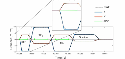
A three-point Dixon UTE sequence with non-selective excitation (Figure 1) was run on a 1.5-T MR-Linac system (Unity, Elekta AB, Stockholm) with two 4-channel phased array coils for an anthropomorphic phantom (3D Abdominal, CIRS, VA) and a volunteer patient at The Royal Marsden NHS Foundation Trust. A 3D stack-of-stars trajectory was employed with parameters: TE1/TE2/TE3 0.14/1.8/3.5 ms, TR 8.1 ms, 2-mm isotropic resolution, field-of-view 50 x 50 x 22.4 cm, acquisition time ~5 min. For each UTE/bipolar echo, 286/504 samples were acquired. In total, 252 radial spokes were sampled in 144 k-space partitions. Spatial saturation pulses were added to remove wrap-around artifacts.The GIRF was characterized as described by Bruijnen et al.9 by applying 21 triangular gradient pulses in two parallel 3-mm thick slices +/- 20 mm from the center of a spherical phantom. Pulses ranged from 4-15 mT/m and were measured with a sampling frequency of 300 kHz. Differences in phase evolution between each slice informed the measured output gradient, and hence the GIRF.
UTE-sequence gradient waveforms were imported from the Paradise pulse programming environment (release 5.3.31; Philips Medical Systems, Best, The Netherlands) into an in-house MATLAB (MathWorks, Natick, MA) reconstruction script. Following correction of gradient waveforms with the GIRF (illustrated in Figure 2), the gradient delay that resulted in optimal image quality was found via systematic variation. Images were reconstructed using k-space sampling locations with and without compensation for GIRFs and gradient delays using an adjoint non-uniform fast Fourier transform (NUFFT).10
Image quality assessment was based on visual evaluations in phantom images of signal uniformity, contrast, and other artifacts such as background signal in air (“halo”) and destructive phase artifacts. A quantitative measure of blurring was made in phantom data by plotting a line profile through a bright edge in a central slice, calculating the derivative, and fitting a Gaussian to estimate the line-spread function of the image.
Results
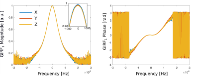
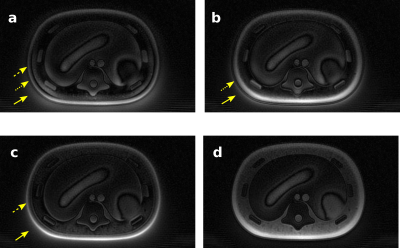
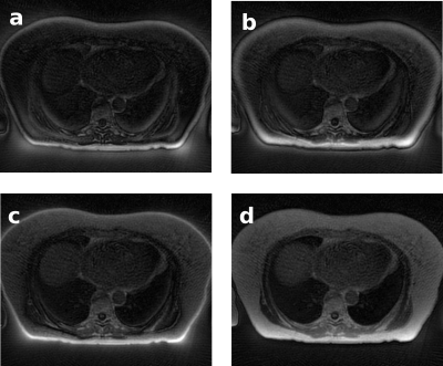
The measured GIRF of the MR-Linac is shown in Figure 3, where it is represented as a complex function in Fourier space. Beyond the ~15 kHz range, the noise in the GIRF measurement increased considerably.The optimal gradient delay was found to be 5 μs. Figures 4 and 5 illustrate UTE images of an anthropomorphic phantom and in human lung, reconstructed with no trajectory corrections applied, with GIRF and delay corrections applied separately and together. Phantom measurements demonstrated improved image quality for data reconstructed with GIRF and gradient-delay corrected trajectories. Where both corrections were applied, images exhibited reduced background signal in air, improved line-spread function (2 mm FWHM compared to 2.7 mm in phantom images), fewer phase-destructive artifacts, and improved uniformity and contrast.
Discussion and Conclusion
The GIRF of the MR Linac system at our institution was measured and used to correct k-space trajectories within an offline, in-house UTE reconstruction. In combination, GIRF and gradient-delay corrected trajectories resulted in high-quality UTE images.The approach used here for correction of UTE images is advantageous for two reasons. First, by treating the MR-Linac gradient system as linear and time-invariant, the GIRF will allow for correction of any combination of gradient waveforms without the need for further measurements.5-8 Second, the measurement method is generally accessible since it does not require specialist hardware such as gradient field probes.11
In future work, corrected UTE reconstruction will be used for generation of sCT images in the thorax, whereby multi-contrast inputs could inform a voxel-based algorithm to classify MR intensity as CT-based tissue type.1-2
Acknowledgements
No acknowledgement found.References
1. Freedman JN, Bainbridge HE, Nill S, et al. Synthetic 4D-CT of the thorax for treatment plan adaptation on MR-guided radiotherapy systems. Phys. Med. Biol. 2019;64.2.
2. Su KH, Friel HT, Kuo JW, et al. UTE-mDixon-based thorax synthetic CT generation. Med. Phys. 2019;46:3520–3531.3.
3. Chang EY, Du J, Chung CB. UTE imaging in the musculoskeletal system. J. Magn. Reson. Imaging 2015;41:870–883.4.
4. Atkinson IC, Lu A, Thulborn KR. Characterization and correction of system delays and eddy currents for MR imaging with ultrashort echo-time and time-varying gradients. Magn. Reson. Med. 2009;62:532–537.5.
5. Vannesjo SJ, Haeberlin M, Kasper L, et al. Gradient system characterization by impulse response measurements with a dynamic field camera. Magn. Reson. Med. 2013;69:583–593.6.
6. Campbell-Washburn AE, Xue H, Lederman RJ, Faranesh AZ, Hansen MS. Real-time distortion correction of spiral and echo planar images using the gradient system impulse response function. Magn. Reson. Med. 2016;75:2278–2285.7.
7. Stich M, Richter JAJ, Wech T, et al. Field camera versus phantom-based measurement of the gradient system transfer function (GSTF) with dwell time compensation. Magn. Reson. Imaging 2020;71:125–131.8.
8. Kronthaler S, Rahmer J, Börnert P, et al. Trajectory correction based on the gradient impulse response function improves high-resolution UTE imaging of the musculoskeletal system. Magn. Reson. Med. 2020;00:1–15.9.
9. Bruijnen T, Stemkens B, van den Berg CAT, Tijssen RHN. Prospective GIRF-based RF phase cycling to reduce eddy current-induced steady-state disruption in bSSFP imaging. Magn. Reson. Med. 2020;84:115–127.10.
10. Fessler JA, Sutton BP. Nonuniform fast Fourier transforms using min-max interpolation. IEEE Trans. Signal Process. 2003;51:560–574.
11. Vannesjo SJ, Haeberlin M, Kasper L, et al. Gradient system characterization by impulse response measurements with a dynamic field camera. Magn. Reson. Med. 2013;69(2):583-593.
Figures


