2982
Clinical MSK Imaging and Challenges at 7T1Radiology, Mayo Clinic, Rochester, MN, United States, 2Neurologic Surgery, Mayo Clinic, Rochester, MN, United States, 3Orthopedic Surgery, Mayo Clinic, Rochester, MN, United States, 4Siemens Medical Solutions USA, Inc., Rochester, MN, United States
Synopsis
Clinical MSK imaging at 7T is advantageous as a result of increased signal to noise ratio, contrast resolution, and spatial resolution compared to lower field strengths. Nevertheless, we have identified several challenges when performing MSK imaging at this field strength including inferior image uniformity, artifacts, coil limitations, and concealed pathology. The purpose of this exhibit is to introduce our early clinical experience with MSK imaging at 7T and illustrate the challenges we have identified.
Introduction
Magnetic resonance imaging at 7T offers superior characteristics, such as increased signal to noise ratio, as compared to lower field strengths. These features are especially pertinent to MSK imaging where detailed evaluation of small structures is required. Even though the application of MSK imaging at 7T is promising, there are unique clinical challenges when imaging at this field strength. The purpose of this exhibit is to introduce our early clinical experience with MSK imaging at 7T and illustrate the challenges we have identified.Methods
Review our early clinical MSK imaging experience and challenges with examinations performed at 7T.Results
Illustrated clinical examples demonstrate the clinical utility, diagnostic advantages, and challenges of performing MSK examinations at 7T.Discussion
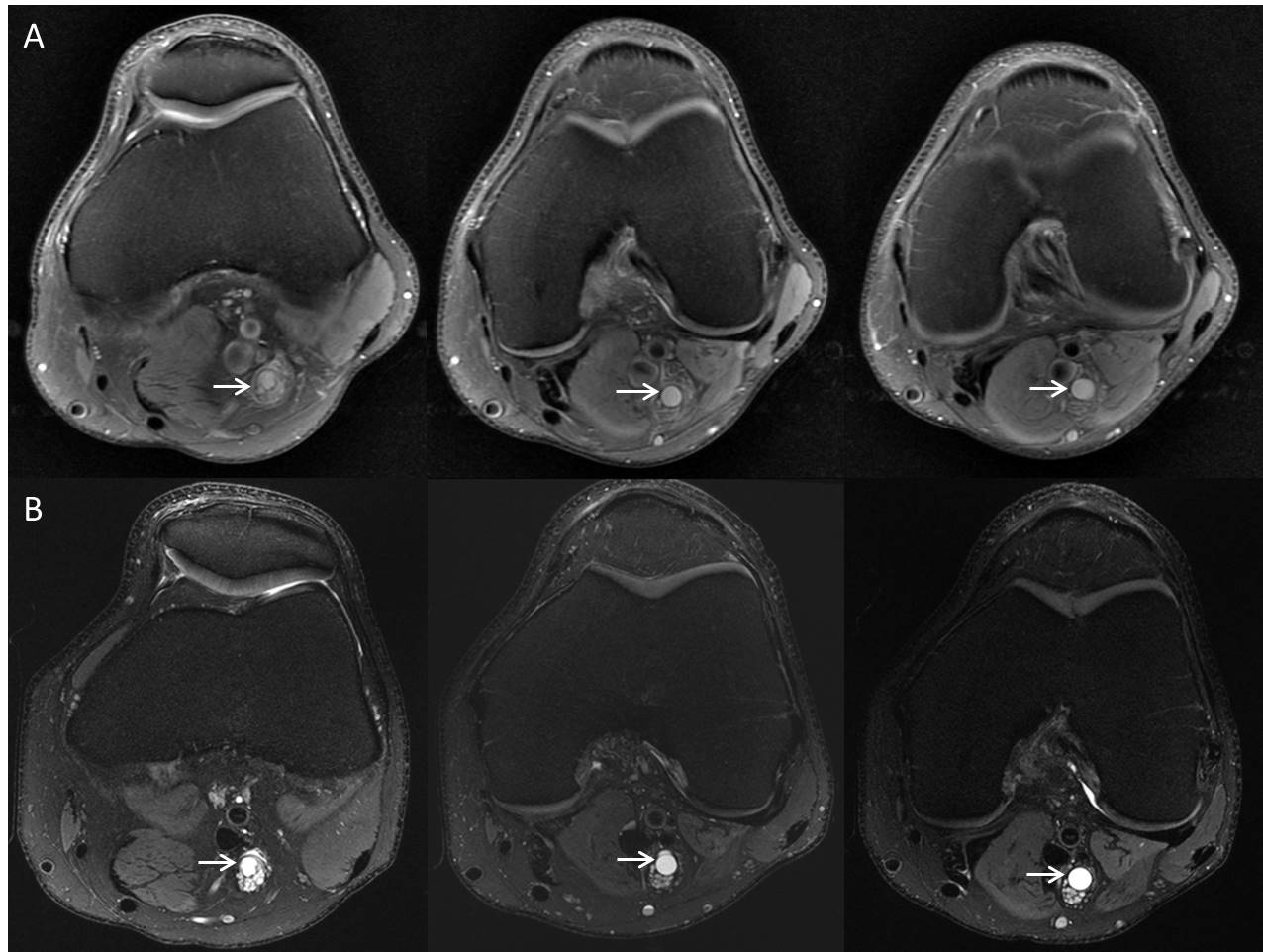
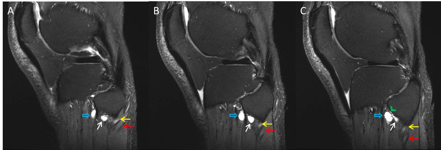
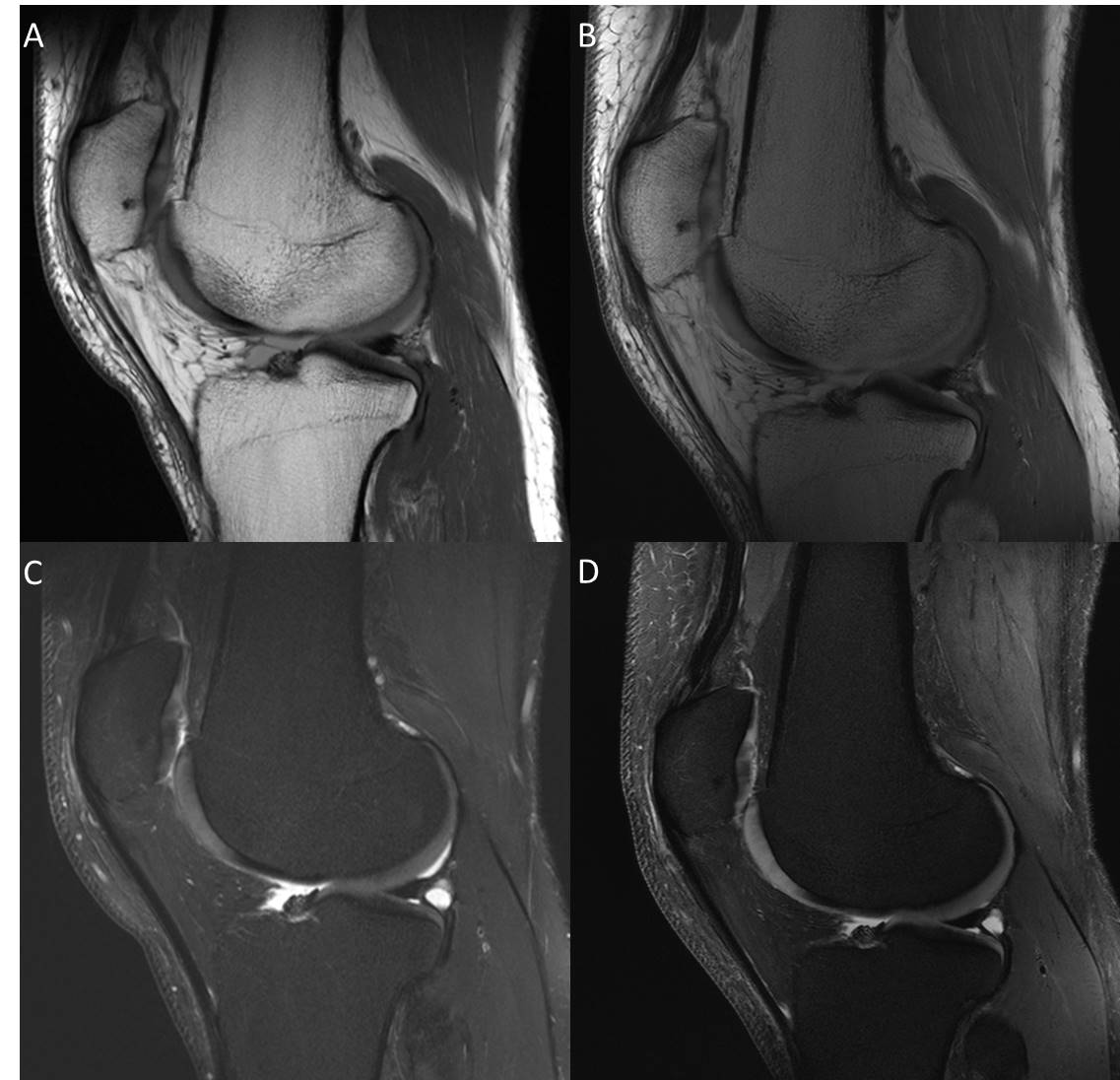
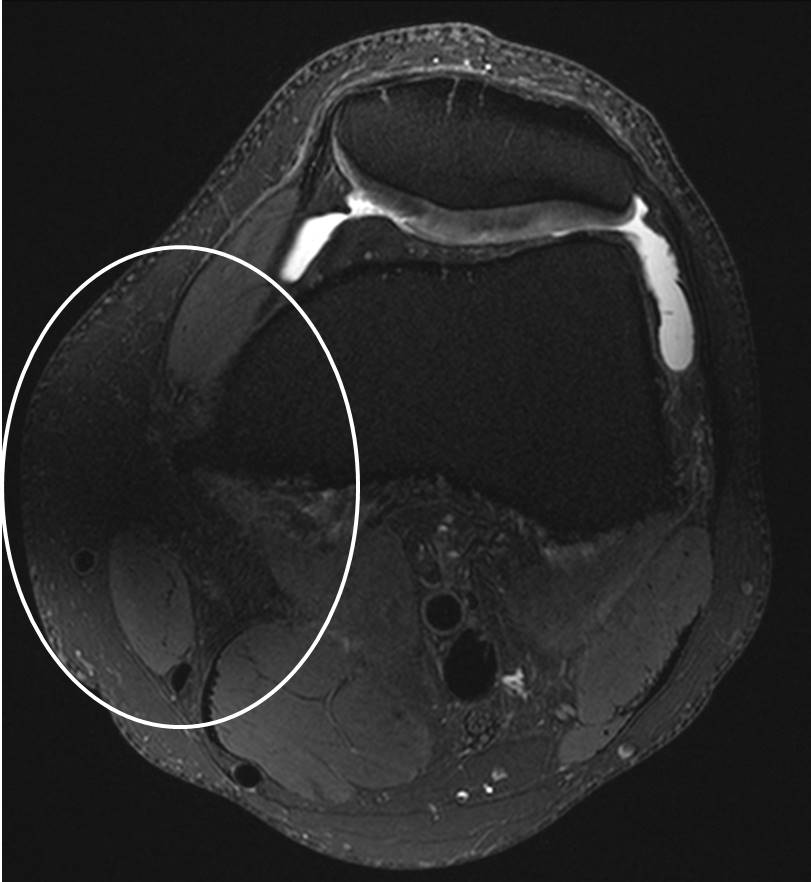
Examinations performed at 7T have the advantage of increased signal to noise ratio, contrast resolution, and spatial resolution compared to lower field strengths. This degree of anatomic and pathologic detail is particularly important with regard to MSK imaging as characterization of ligamentous, cartilaginous, and peripheral nerve pathology can have management implications and influence surgical and biopsy planning. Despite these advantages, there are several clinical challenges and limitations to imaging at 7T. Patient safety concerns include the potential to cause RF-induced tissue heating near implanted metallic devices and increased effects on the vestibular system1,2. Poor B1+ field uniformity is an inherent challenge which affects image quality, but can be mitigated using high permittivity dielectric pads3. MSK MR examinations rely on non-fat suppressed imaging to detect common pathology such as meniscal tears which may be less conspicuous at 7T due to alterations in tissue contrast compared with conventional imaging at 1.5T or 3T. Artifacts such as chemical shift and fine line artifacts are more apparent at 7T and can be difficult to manage. Coil limitations restrict the number of joints which can be evaluated, alter anatomic relationships as a result of coil construction, and require modified positioning4. Routine MSK pathology, such as meniscal tears, are sometimes less conspicuous at 7T and require innovative post-processing techniques to mitigate5.Conclusion
Increased signal to noise ratio and resolution are the primary advantages to imaging at 7T with important applications to clinical MSK imaging. Despite the evolution in technology, there are unique challenges facing MSK imaging at 7T which require further innovation and collaboration to resolve.Acknowledgements
NoneReferences
1. Fagan AJ, Amrami KK, Welker KM, Frick MA, Felmlee JP, Watson RE, Jr. Magnetic Resonance Safety in the 7T Environment. Magnetic resonance imaging clinics of North America. 2020;28(4):573-582.
2. Fagan AJ, Bitz AK, Björkman-Burtscher IM, et al. 7T MR Safety. Journal of Magnetic Resonance Imaging. 2020.
3. Fagan AJ, Welker KM, Amrami KK, et al. Image Artifact Management for Clinical Magnetic Resonance Imaging on a 7 T Scanner Using Single-Channel Radiofrequency Transmit Mode. Invest Radiol. 2019;54(12):781-791.
4. Chebrolu VV, Kollasch PD, Deshpande V, et al. Uniform combined reconstruction of multichannel 7T knee MRI receive coil data without the use of a reference scan. J Magn Reson Imaging. 2019;50(5):1534-1544.
5. Chebrolu VV, Kollasch PD, Stinson E, et al. Subtle Intensity Graduating Homomorphic Transform (SIGHT) with Small Percentage Fat-saturation to Improve Conspicuity of Meniscal Tears at 7T. Proceedings_ISMRM. 2019:2801.
Figures