2924
Restraint System for Motion Reduction in MRI studies of Awake Mice1Biomedical Engineering, Emory University/Georgia Institute of Technology, Atlanta, GA, United States
Synopsis
We designed a head restraint system for image acquisition in awake mouse fMRI studies that minimized head motion. The system consists of a head implant, combined with a customized cradle and head holder. Two distinct head implant designs are tested to evaluate if the motion goal for the system is achieved.
Introduction
The use of animals in functional magnetic resonance imaging (fMRI) studies has led to increased understanding of functional neural networks in the cerebral cortex. Most fMRI studies are performed in anesthetized animals, but anesthetics affect neural activity and hemodynamics and preclude the use of behavioral tasks.1,2 For this reason, researchers are beginning to perform fMRI in awake mice. While several groups have created acclimation and restraint systems for awake animal studies, motion remains a major challenge, and none of the current approaches have been able to reduce movement below 200 microns.3 We designed a specialized head implant and holder to reduce motion in these scans.Methods
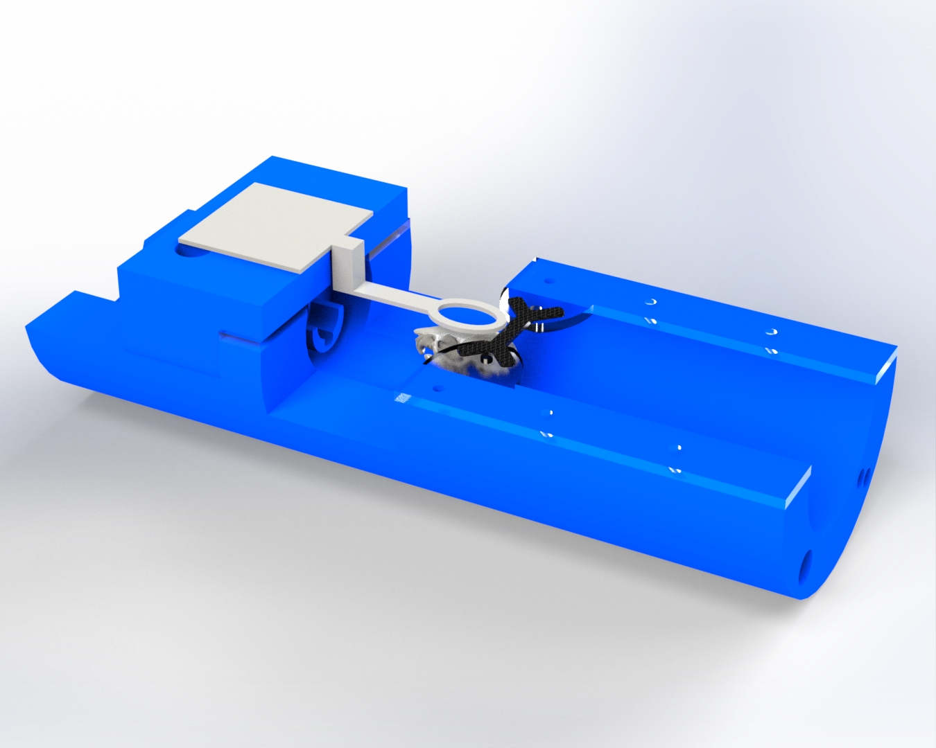
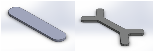
This study proposes a cradle restraint setup, as shown in Fig. 1, to restrict animal motion to less than 110 microns for scans with voxels of 330 microns or greater using an implanted head bar and supports. The main cradle is 3D printed out of PLA and has a curved base so that it can fit into the tube that is inserted into the MRI scanner. Attached to the cradle is a coil holder constructed of PLA. The coil holder supports the coil for image acquisition and routes a water tube for fluid administration towards the animal’s head during imaging to deliver liquid rewards. The coil has been optimized to be the minimum size needed to fully image the animal’s brain. Acrylic brackets are attached on the opposite side of the cradle to hold the carbon fiber head bar in place with a nut and bolt when the animal is in the restraint. A paw bar is also embedded in the base of the cradle for the animal’s comfort during imaging.Two different head bar designs (I-shaped and X-shaped, as shown in Fig. 2) were implanted on the skull of the animals using dental cement. Head bars were used rather than a post to increase the points of contact for head fixation. The geometry of the head bars was determined using static simulations in SOLIDWORKS to test the effects of rotational torques on the stress, strain, and deformation of the setup. The animals also underwent a habituation process to decrease stress and overall motion prior to scanning. Habituation was a 4-week process that consisted of three distinct phases: basic handling with a trainer, head fixation, and head fixation with scanner noises.
Four mice 20-30g (2 female) underwent multiple scan sessions in a 9.4T Bruker BioSpin MRI between June 2019 and December 2020. Two animals were head-fixed using the I-shaped head bar and two were head-fixed using the X-shaped bar for all sessions. Anesthesia was not required to place the animals in the head restraint. Functional images were acquired using a gradient-echo (GE) EPI sequence (TR/TE = 1000ms/15ms) with 20 slices in each repetition and 333µm isotropic voxel size. 300 repetitions (5 minutes of data) were acquired for each functional scan. 9 scans were collected in each scanning session. The motion parameters for each scan were analyzed using SPM-12 and a custom MATLAB script that performed realignment and removed signal drift.
Results and Discussion
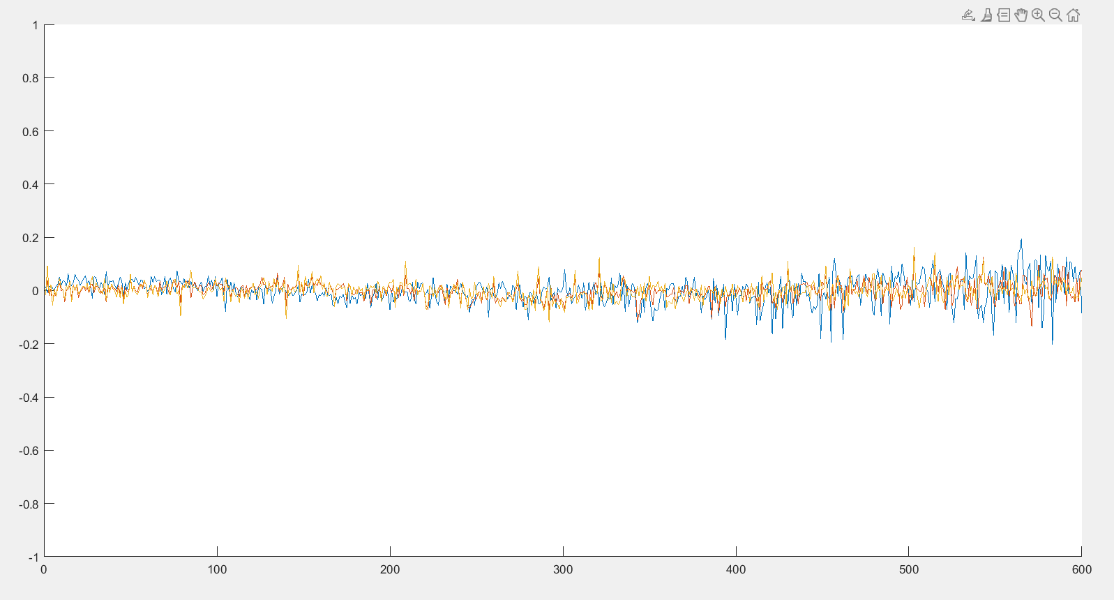
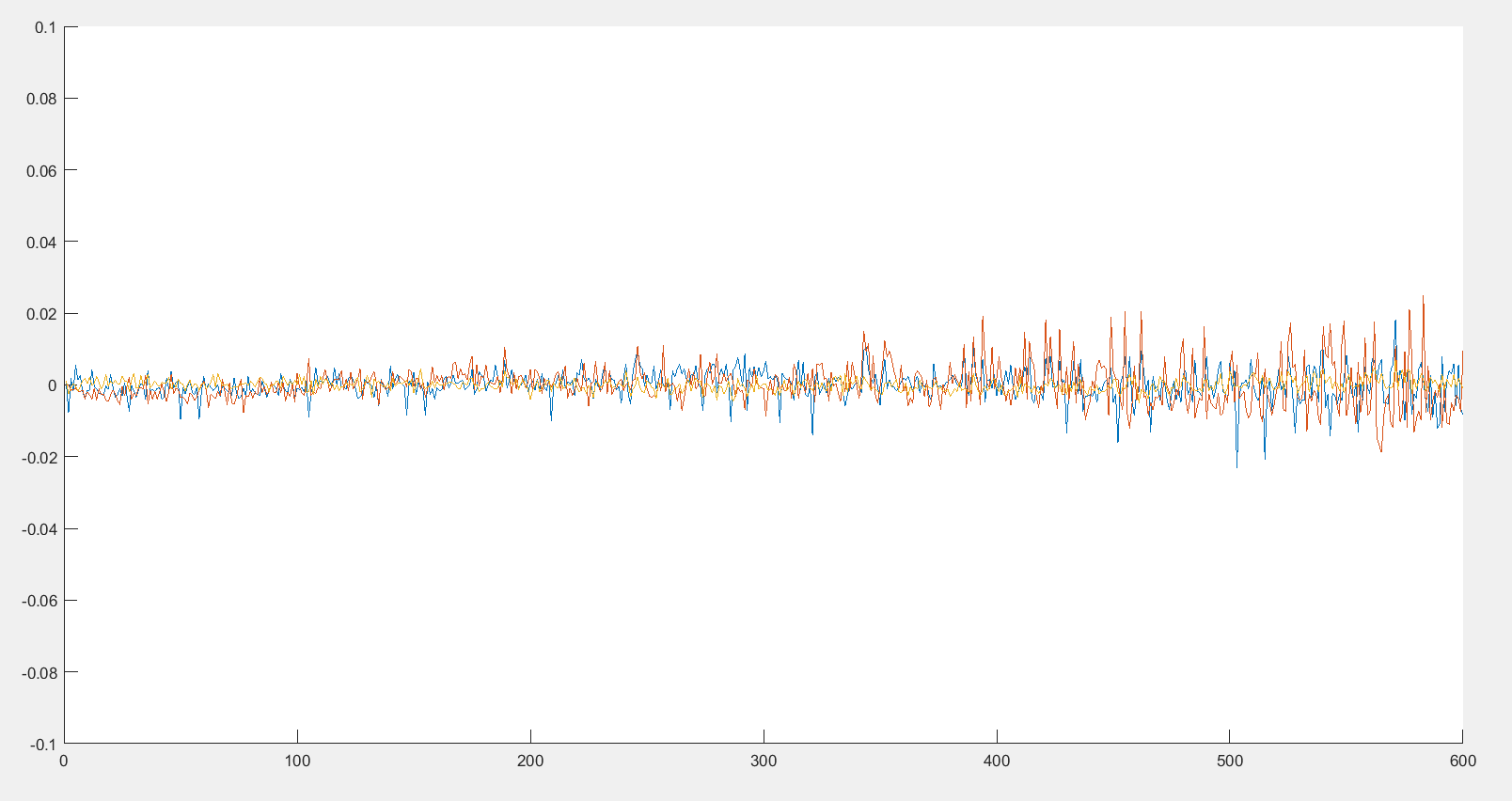
The linear standard deviations of translation in the x, y, and z directions were analyzed to study overall scan displacement and compare the two head bar designs. The mean displacement data in the x, y, and z directions for the I-shaped head bar were 0.166 mm, 0.743 mm, and 0.143 mm, respectively. The standard deviation of displacement for the x, y, and z directions were 0.104 mm, 0.745 mm, and 0.110 mm, respectively. Preliminary data from the X-shaped head bar yielded mean displacements in the x, y, and z directions of 0.235 mm, 0.665 mm, and 0.060 mm, respectively. The standard deviation of the displacement for the x, y, and z directions were 0.129 mm, 0.298 mm, and 0.031 mm, respectively.The average displacement for preliminary data in both the I-shaped and X-shaped head bars remained above the target goal of 110 microns. Further data collection will be necessary to evaluate if both designs meet the set design criteria as well as to determine if one design has a statistically significant improvement in motion in comparison to the other. A potential source of error in our preliminary data is due to unintentional contact between the animal’s back and the RF coil which created disturbances in the signal.
Conclusion
Although our specific motion goal has yet to be reached, our results are promising and we will continue to evaluate sources of motion. Several additional designs for the cradle and head bar are proposed and being tested for continuing progress. A second generation of the cradle has been designed in SOLIDWORKS and 3D printed to feature a rectangular base, angled body tube, and additional paw bar ridges to increase animal comfort and decrease potential error sources. Additionally, a third point of stability system featuring a screw and nut that connect in front of the head bar is being tested to provide additional stability during scanning. With the results from this stability test, we hope to incorporate the concept into the development of a third type of head bar.Acknowledgements
This work was supported by the National Science Foundation BCS INSPIRE 1533260, National Institutes of Health R01NS078095 and 1R01MH111416-01.References
1. M. Desai, I. Kahn, U. Knoblich, J. Bernstein, H. Atallah, A. Yang, N. Kopell, R. L. Buckner, A. M. Graybiel, C. I. Moore, E. S. Boyden, “Mapping brain networks in awake mice using combined optical neural control and fMRI,” Journal of Neurophysiology, vol. 105, no. 3, pp. 1393–1405, 2011.
2. Z. Liang, J. King, and N. Zhang, “Intrinsic Organization of the Anesthetized Brain,” Journal of Neuroscience, vol. 32, no. 30, pp. 10183–10191, 2012.
3. J. A. King, T. S. Garelick, M. E. Brevard, W. Chen, T. L. Messenger, T. Q. Duong, and C. F. Ferris, “Procedure for minimizing stress for fMRI studies in conscious rats,” Journal of Neuroscience Methods, vol. 148, no. 2, pp. 154–160, 2005.
Figures