2515
Wirelessly controlled stand-alone automatic RF tuning and matching system for preclinical imaging at 7T1Biomedical Engineering, Arizona State Universirty, Tempe, AZ, United States, 2Biomedical engineering, Arizona State University, Tempe, AZ, United States
Synopsis
Impedance matching of RF coils during MR imaging is crucial to improve SNR and would enhance power transfer efficiency for transmit coil reducing wastage of RF power. This work focuses on presenting a stand-alone system with wireless Automatic Tuning and Matching system (ATM) for transmit (Tx)-only and receive (Rx)-only coils separately. We present separate Tx-only and Rx-only coils with high power and low power ATMs respectively along with a self-triggering circuit for Rx coil decoupling while high power Tx signal is active.
Introduction
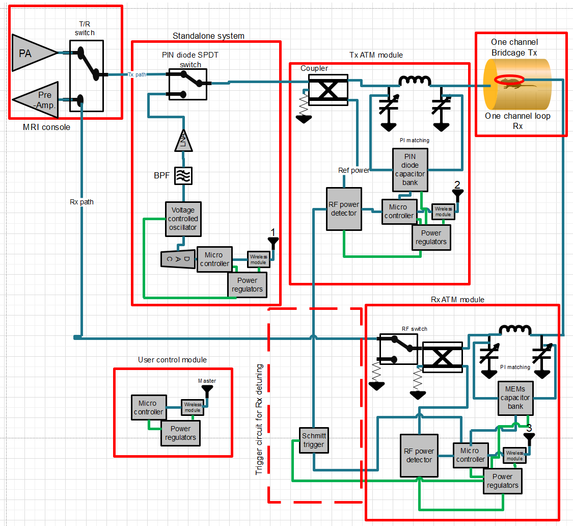
Manual tuning and matching of RF coils requires substantial time. Most coil systems present themselves with a sub-optimal matching condition after loading the subject. This creates an impedance mismatch and loss of signal strength that cannot be recovered by a pre-amplifier, thus deteriorating the SNR substantially. Existing automatic tuning and matching systems use control signals from the MRI console requiring them to have long cables and synchronization. External signal connection from the MRI console is not necessary to operate this stand-alone system because of the ability to replicate the RF pulse and a built-in triggering circuit. This complete stand-alone system being wireless, would remove the requirement of long cables and offer user-friendly functions. The triggering circuit is used to decouple the Rx coil during Tx operation. Previously, studies have used a transceiver coil ATM systems1, 2 and a VCO based ATM system was introduced in the past but was limited to low power receive only coils due to the usage of varicaps3. This study uses a PIN diode based capacitor array for high power transmit coil and MEMs switch based capacitor array for low power receive coil respectively (Fig.1). The two separate coils are tuned and matched sequentially using optimization algorithm with wirelessly enabled microcontroller, which diminishes the time and effort needed to carry out this process manually.Method
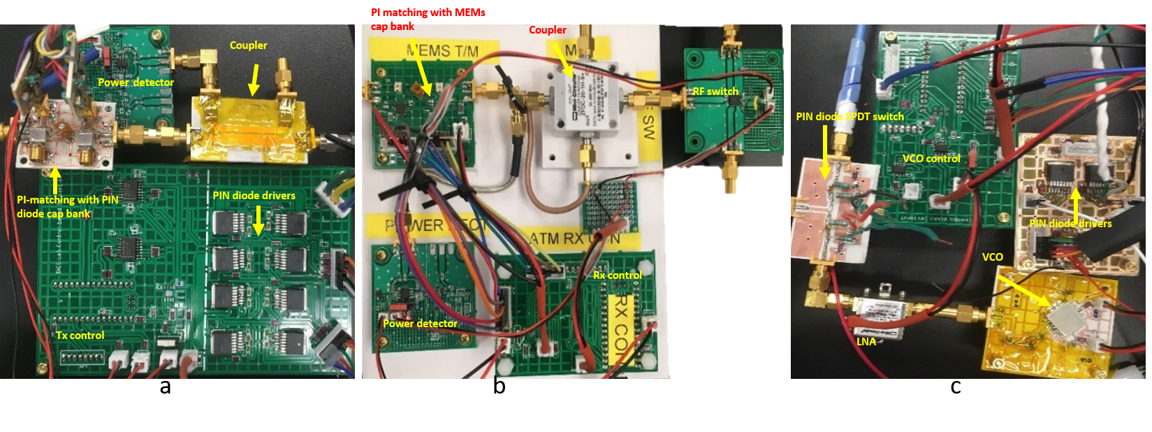
A single channel half head surface coil was used as a transmit coil and single channel small loop coil was used as a receive coil to conduct the bench test. A two-port VNA (FieldFox N9923A, Keysight Technologies, USA) is used to get the S-parameter results. For the transmit coil tuning and matching, a VCO (CVC055CW-250-450, Crystek Crystal Corp., USA) is used to generate RF CW signal at +19 dBm. A PIN diode (MA4P7446F-1091T, Macom, USA) based Single Pole Double Throw (SPDT) RF switch is used to switch the main signal path between MRI console and stand-alone system, called the ATM mode. A Pi-matching network with PIN diode based capacitor (1111C series Non-magnetic, PassivePlus, USA) bank with fixed capacitors is used to generate 256 combinations of tuning and matching conditions. A bi-directional coupler is used to tap the reflected power using a logarithmic power detector (AD8307, Analog Devices, USA) and fed to a microcontroller (Arduino NANO, Arduino, ITALY) which also controls the toggling of the PIN diodes using a separate interface consisting of RS-232 drivers (MAX234CWE, Maxim Integrated, USA) and high-current, high voltage Opamp (OPA552, TI, USA) (Fig. 2a, 2c). Upon the completion of tuning and matching for the transmit coil, receive coil tuning is started. Here, we use an RF switch (HSW2-272VHDR+, Mini circuits, USA) to switch the receive coil between MRI console and power measurement mode. For tuning and matching of the Rx coil, power radiated by the Tx coil is detected, where the Rx coil acts as a pickup probe. This is the dual function of the Rx coil. An optimal impedance match condition is selected by adjusting the capacitance values using two MEMs (ADGM1304, Analog Devices, USA) SP4T switches. Once the tuned and matched state of the receive coil is attained, the system automatically switches back to MRI console, ready for normal imaging process (Fig. 2b). During the imaging, the same power detector along with a triggering circuit is used to replicate the RF gating signal, which would allow the receive coil to decouple during the transmit cycle. This is what gives our system a unique ability to not use triggering signal from the console for Rx decoupling. A user end module with “master” wireless chip (NRF24L01+, Nordic Semiconductors, Norway) along with switches to start and stop ATM was used to conduct the bench test.Results and Discussion
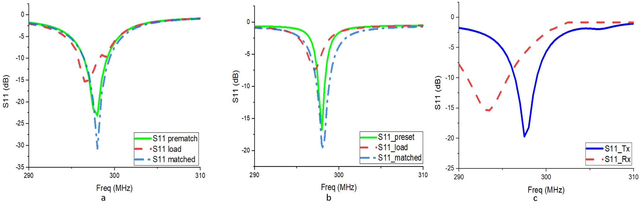
Bench test results show that return loss of 30 dB (Fig. 3a) was achieved after the Tx ATM and around 20 dB (Fig. 3b) was achieved after the Rx ATM system. A preset state is set in the Rx optimization algorithm to decouple the coil whenever the gating signal is in transmit mode (Fig. 3c). This method of extracting the gating signal will help in automatically decoupling the receive coil through the imaging sequence.Conclusion
We present a fully working prototype for a stand-alone automatic tuning and matching system with wireless control. This work on a single channel coil establishes the foundation for a wireless tuning and matching system, which can be easily be scaled to a multichannel system.Acknowledgements
No acknowledgement found.References
1. Sohn, S. M., DelaBarre, L., Gopinath, A., & Vaughan, J. T. (2015). Design of an Electrically Automated RF Transceiver Head Coil in MRI. IEEE transactions on biomedical circuits and systems, 9(5), 725–732. https://doi.org/10.1109/TBCAS.2014.2360383
2. Muftuler, L. T., Gulsen, G., Sezen, K. D., & Nalcioglu, O. (2002). Automatic tuned MRI RF coil for multinuclear imaging of small animals at 3T. Journal of Magnetic Resonance, 155(1), 39–44. https://doi.org/10.1006/jmre.2002.2510
3. M. Pavan, R. Lüchinger, and K. P. Pruessmann. (2011). Fast automatic matching control: Technical advances and initial results of SNR optimization. Proc ISMRM.
Figures