2508
Interleaved nine-leg birdcages for simultaneous geometric decoupling from a double tuned planar array1Biomedical Engineering, Texas A&M University, College Station, TX, United States, 2Electrical and Computer Engineering, Texas A&M University, College Station, TX, United States
Synopsis
This work describes two interleaved nine-leg linear birdcages for geometric decoupling from a double-tuned planar array for 1H and 23Na at 4.7T. An asymmetric design was chosen to create aligned fields to simultaneously decouple the receive array from the two transmit birdcages. This straightforward design provides sufficient decoupling from coils in all six positions in the final array configuration and enables multinuclear multichannel imaging experiments.
Synopsis
This work describes two interleaved nine-leg linear birdcages for geometric decoupling from a double-tuned planar array for 1H and 23Na at 4.7T. An asymmetric design was chosen to create aligned fields to simultaneously decouple the receive array from the two transmit birdcages. This straightforward design provides sufficient decoupling from coils in all six positions in the final array configuration and enables multinuclear multichannel imaging experiments.Introduction
The work presented here revolves around the need to decouple the transmit coil from a planar array without the complexity of active detuning. In order to conduct this work, a double tuned transmit coil was constructed that created a homogeneous field over the area of the double tuned planar array in order to solely geometrically decouple from the array and therefore eliminate the additional complexities of active detuning. Several designs have been proposed previously for double tuned birdcages including an alternating rung1, four ring2, and concentric coils3. While asymmetric birdcages designs have occasionally been used for optimization of coils to fit around patient hardware in the scanner 4, conventional birdcages are constructed in a circular form using an integer multiple of four legs to create a highly symmetric structure 5. However, it is difficult to achieve the required parallel linear fields at the two different frequencies over the same field of view using these symmetric approaches without overlapping legs between the two birdcage coils, leading to higher losses from the shielding effects of the overlapping legs and/or the trapping components on individual legs. In this work we present a design of interleaved nine-leg birdcages to achieve simultaneous geometric decoupling from a planar array at two frequencies in a low complexity manner.Methods
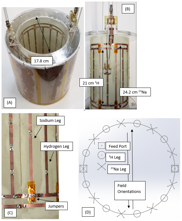
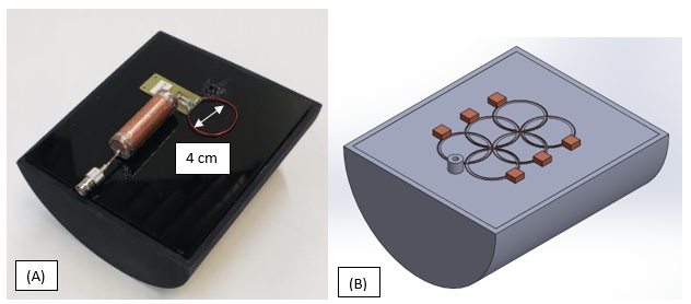
The coils were constructed on flexible copper clad FR4 and mounted on an acrylic cylinder with “jumpers” to bridge the end rings of the hydrogen coil over the legs of the sodium coil. Both coils were constructed on the same 17.8cm diameter acrylic former. The hydrogen coil (200 MHz) was constructed using a bandpass design with a 21cm length and the sodium coil (52.9 MHz) was constructed using a high pass design with a 24.2cm length. The coils were populated with distributed capacitors (1111C, Passive Plus) and matched and tuned with variable capacitors (NMAT 40HVE 1712, Voltronics Corp.). Once the coil was matched and tuned for both frequencies, the distributed capacitances were shifted slightly on one leg to either side of the port for the sodium birdcage. This shifted the field orientations to fine tune them to be precisely antiparallel. A shield was constructed by mounting overlapping copper sheets inside a 25.4cm acrylic cylinder. The coil configuration and shield can be seen in Figure 1.A single 4cm diameter receive test coil was constructed with 24 AWG wire and connected to an FR4 match/tune board. Variable capacitors (SGC3S, Sprague Goodman) were used to double tune each loop at the 1H and 23Na frequencies. A phantom was designed and 3D printed to create a half cylindrical former with a flood region containing a solution of NaCl (σ=0.73 S/m, εr = 78) and to provide stable positioning of the up to six receive elements. Photographs of the phantom and a rendering of the six element receive array positioning can be seen in Figures 2A and 2B respectively. Bench measurements were used to measure Q and coupling was measured with S21 bench measurements acquired at both frequencies between the birdcages and the test receive element translated to each of the six array locations. Transmit/Receive 1H images were acquired on a 4.7T Varian Inova scanner with the test element in place and terminated to verify a homogeneous field and geometric decoupling. Birdcage transmit with test element receive was performed at both 1H and 23Na frequencies to verify performance at both frequencies. Hydrogen data was acquired using a standard spin echo pulse sequence (TR/TE: 1000ms/30ms, m: 256x256, FOV: 160mmx160mm, Slice thickness: 1mm). Sodium images were acquired using a gradient echo pulse sequence (TR/TE: 30ms/3.5ms, N: 64 averages, m: 64x64, FOV: 160mmx160mm, Slice thickness: 20mm, Spectral width: 20kHz).
Results
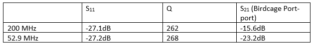
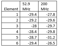
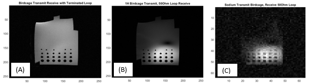
A Q better than 260 was shown for the birdcages at their respective frequencies, with better than -15 dB of decoupling at both frequencies at the two birdcage ports (Table 1). Decoupling measurements (Table 2) show better than -26 dB of geometric decoupling for all six element locations at both frequencies. Imaging data further validates these conclusions. Figure 3A shows a birdcage T/R image acquired with the test element in place and terminated in 50Ω, validating that the homogeneity of the field is not significantly affected by coupling with the loop. Figures 3B and 3C show images receiving with a single loop for hydrogen and sodium, respectively, indicating appropriate transmit performance at both frequencies.Conclusion
The nine-leg interleaved birdcage design allowed for antiparallel fields at two different frequencies that can not only decouple the two birdcages from each other, but also from all six elements of the planar array at both frequencies. Future work includes populating the system with the full six element array and using it for testing dual tuned arrays.Acknowledgements
The authors gratefully acknowledge funding for this project provided by NIH grant number R21EB028516.References
1. Giovannetti, G. et al. Design and simulation of a dual-tuned 1H/23Na birdcage coil for MRS studies in human calf. Applied Magnetic Resonance 46, 1221-1238, (2015).
2. Murphy-boesch, J., Srinivasan, R., Carvajal, L. & Brown, T. R. Two Configurations of the Four-Ring Birdcage Coil for 1H Imaging and 1H-Decoupled 31P Spectroscopy of the Human Head. Journal of Magnetic Resonance, Series B 103, 103-114, (1994).
3. Brand, R., Webb, A. & Beenakker, J.-W. M. Design and performance of a transformer-coupled double resonant quadrature birdcage coil for localized proton and phosphorus spectroscopy in the human calf muscle at 7 T. Concepts in Magnetic Resonance Part A 42, 155-164 (2013).
4. De Zanche, N., Yahya, A., Vermeulen, F. E. & Allen, P. S. Analytical approach to noncircular section birdcage coil design: verification with a Cassinian oval coil. Magn Reson Med 53, 201-211, (2005).
5. Hayes, C. E., Edelstein, W. A., Schenck, J. F., Mueller, O. M. & Eash, M. An efficient, highly homogeneous radiofrequency coil for whole-body NMR imaging at 1.5 T. Journal of Magnetic Resonance (1969) 63, 622-628, (1985).
Figures