2507
Analysis of common-mode rejection ability and Insertion Loss of Dual band Lattice Balun with non-ideal components1Vanderbilt University Institute of Imaging Science, Nashville, TN, United States, 2Department of Radiology and Radiological Sciences, Vanderbilt University, Nashville, TN, United States
Synopsis
A dual band Lattice balun was proposed previously, which holds the promise of removing common mode current for both frequencies in dual-tuned MRI coils with a single interfacing unit. However, the previously fabricated unit had a considerable insertion loss at the proton Larmor frequency. In this work, we analyzed how each lumped element will affect this device's performance and optimized the circuit performance based on the analysis.
Purpose
Dual-tuned MRI coils are highly desired in MRI and MRS to meet the need for acquiring signals from multiple nuclei in the same study [1-3]. Due to the presence of two resonate frequencies, each coil is required to connect cable traps or balun circuits for both frequencies to avoid the cross-talk, reduce the signal-to-noise loss and ensure patient safety [4-6]. The dual-band Lattice balun is a novel method that inherits the benefits of standard Lattice balun (small footprint and easy to integrate with feed board) and meanwhile exhibits the ability to suppress the common mode current at the Larmor frequencies of both nuclei [7]. However, in dual-band Lattice balun, there are up to 8 lumped elements that complicate the practical fabrication and may degrade the performance due to non-ideal components. To better understand such a dual-band balun and give guidance to practical fabrication, in this work, we investigated how the balance of two branches and the circuit's insertion loss will be affected by using non-ideal components (up to 5% tolerance).Methods
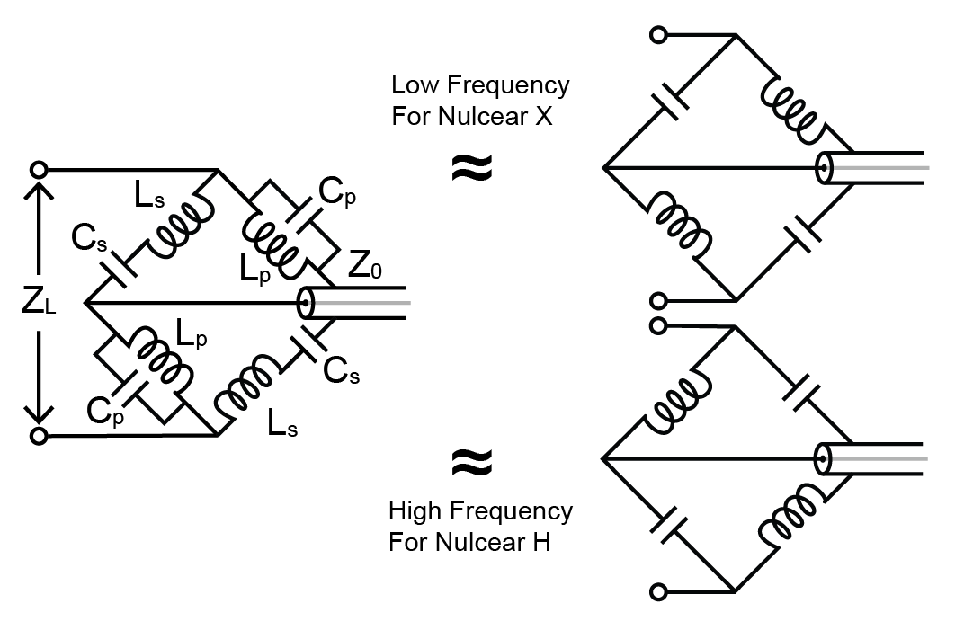
Figure 1 shows the schematic of the dual-band balun [1]. It consists of two branches from balanced ports to the unbalanced port. It can be seen as a first-stage 90-degree lattice balun at each frequency.EM Simulation setup
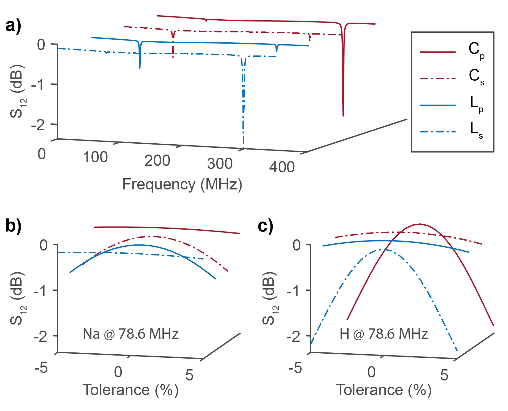
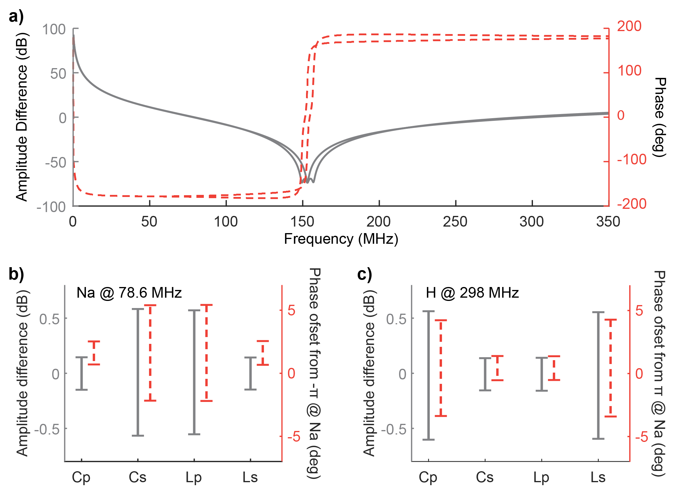
We simulated a dual-band balun circuit for a 7 T proton (Larmor frequency 298 MHz) and sodium imaging (Larmor frequency 78.6 MHz) with the Ansys EM package (Designer, Ansys, Canonsburg, PA). Inductors were set with a serial resistance (0.3 Ohm at 298 MHz, 0.6 Ohm at 78.6 MHz) based on the manufacturer's datasheet. We varied two copies of each component in two different ways, either multiplying the variation factor both from 0.95 to 1.05 or oppositely multiplying these factors, i.e., one from 0.95 to 1.05 while the other from 1.05 to 0.95. The balun's insertion loss was evaluated directly by the transmission coefficient (S21) between the balanced and unbalanced ports. The common-mode rejection ability was evaluated indirectly by the amplitude and phase balance between two balanced ports.
Fabrication and Evaluation
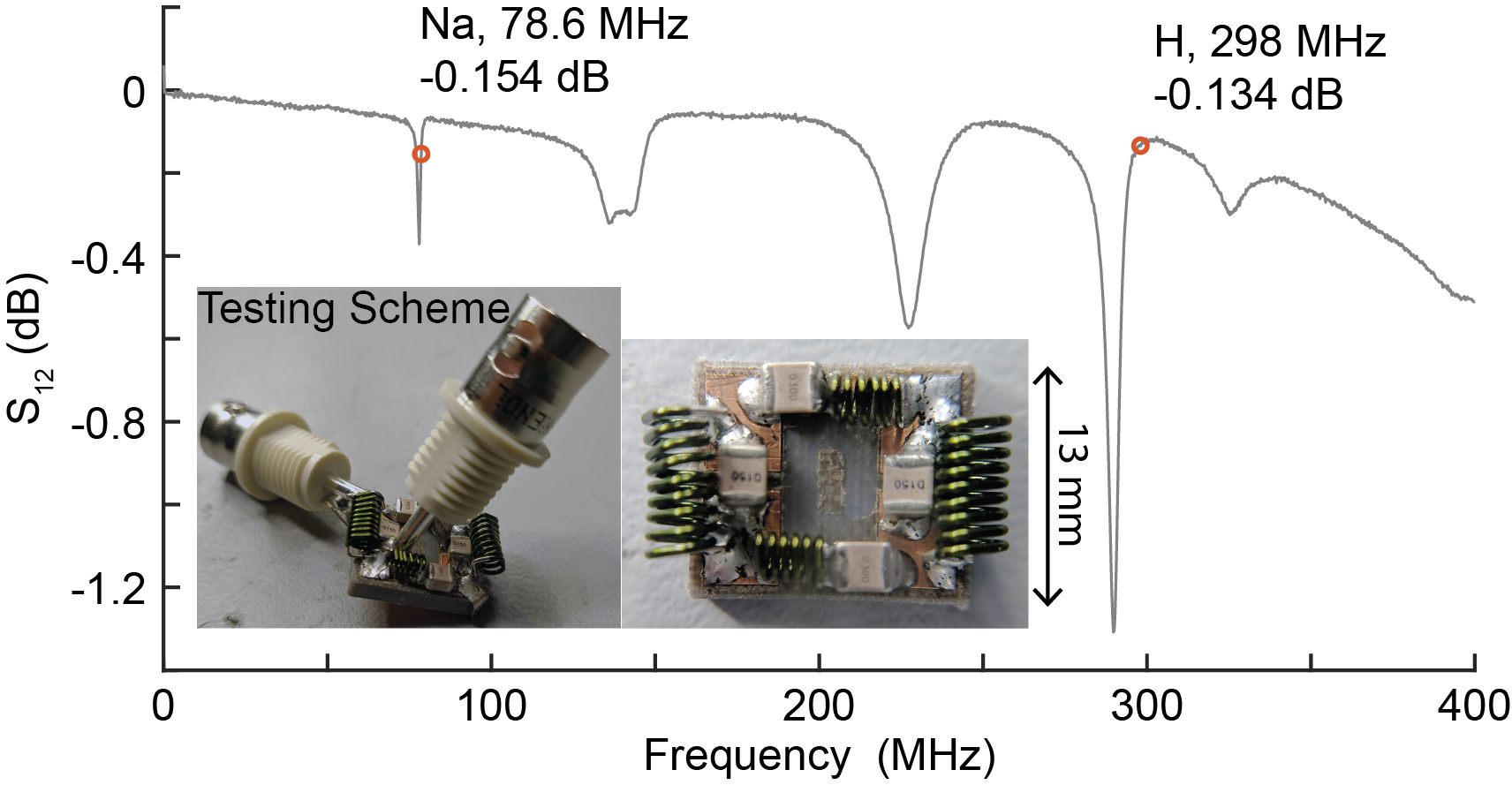
An improved miniatured dual-band balun (dimension 12.75 x 15.15 mm2) was fabricated on a Rogers CUCLAD 217 double-side board. All lumped elements' values were adjusted based on the finding in simulation results (described later) to achieve a high common-mode rejection ratio (CMRR) and low insertion loss. The values of practical components are: Lp = 82 nH, Ls = 39 nH, Cp = 15 pF, Cs = 30 pF, while the calculated values are: Lp0 = 14.5 nH, Ls0 = 36.3 nH, Cp0 = 14.5 pF, Cs0 = 29.8 pF. Capacitors were chosen from a pool of 5%-tolerance high-Q and non-magnetic capacitors (1111C series, PPI, Huntington, NY). Inductors are modified from air-core RF inductors from CoilCraft (Cary, IL). The insertion loss and CMRR were tested by a calibrated four-port Vector Network Analyzer (Keysight, Santa Rosa, CA).
Results and Discussion
SimulationPartial simulation results are shown in Figure 2 (insertion loss) and Figure 3 (CMRR). Varying lumped elements in the opposite direction (for example, increasing Lp in one branch while decreasing it in the other branch) led to higher insertion loss, as shown in Figure 2a. Figures 2b and 2c show the insertion loss at sodium and proton frequency with different element value variation levels. It is found that Cp and Ls values mainly impact the insertion loss at proton frequency, while Cs and Lp affect the sodium frequency more. A similar phenomenon was found with the CMRR simulation. As shown in Figure 3, Cp and Ls determine CMRR at proton frequency, while Cs and Lp are more prominent for sodium frequency. These results are expected by examining the impedance equations. The $$$1/j\omega C_s$$$ and $$$1/j\omega L_p$$$ terms are more effective at low frequencies while $$$j\omega L_s$$$ and $$$j\omega C_p$$$ are more pronounced at high frequencies.
Fabricated device and bench test
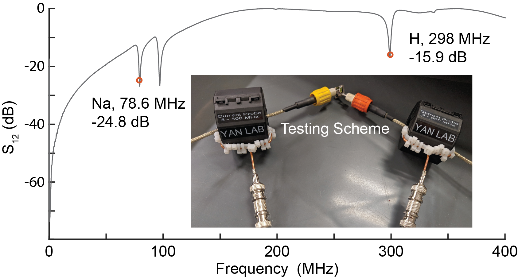
The measured insertion loss and CMRR of fabricated balun are shown in Figures 4 and 5, respectively. Since the discrete values from commercial parts differ from that of the calculated value, the inductors are varied empirically to meet the desired results. Based on the simulations and equations shown above, increasing Lp's values will increase the frequency of the CMRR peak for Na while Ls for H and vice versa. The resulted insertion losses are -0.154 dB for Na and -0.134 dB for H. The CMRRs are 24.8 dB for sodium and 15.9 dB for proton. These combined results showed that this dual tuned balun is low loss and has high CMRR at desired frequencies. It is also easy to fabricate the balun for other frequencies.
Conclusion
We have constructed a high-performance dual-band Lattice balun with the guidance of circuit analysis and optimization. This balun has a low insertion loss of -0.154 dB (sodium) and -0.134 dB (proton) and a high CMRR of 24.8 dB (sodium) and 15.9 dB (proton).Acknowledgements
This work was supported by NIH R21 EB029639.References
1. Shen G X, Boada F E, Thulborn K R. Dual-frequency, dual-quadrature, birdcage RF coil design with identical b1 pattern for sodium and proton imaging of the human brain at 1.5 T. Magn Reson Med 1997;38: 717–725.
2. Wiggins G C, Brown R, Fleysher L, Zhang B, Stoeckel B, Inglese M, Sodickson D K. A nested dual frequency birdcage/stripline coil for sodium/proton brain imaging at 7T. In Proceedings of the 18th Annual Meeting of ISMRM, Stockholm, Sweden, 2010. Abstract 1500.
3. Shajan G, Mirkes C, Buckenmaier K, et al. Three‐layered radio frequency coil arrangement for sodium MRI of the human brain at 9.4 Tesla. Magnetic resonance in medicine 75.2 (2016): 906-916.
4. Dabirzadeh A, McDougall M P. Trap design for insertable second-nuclei radiofrequency coils for magnetic resonance imaging and spectroscopy. Conc Magn Reson B. 2009;35B:121–132
5. Wilcox M, Wright S M, McDougall M P. Multi-Tuned Cable Traps for Multinuclear MRI and MRS. IEEE Transactions on Biomedical Engineering. 2019 Aug 7;67(4):1221-8.
6. Enríquez Á G, Vincent J M, Rispoli J V. Dual-Tuned Removable Common-Mode Current Trap for Magnetic Resonance Imaging and Spectroscopy. In2019 41st Annual International Conference of the IEEE Engineering in Medicine and Biology Society (EMBC) 2019 Jul 23 (pp. 6802-6805). IEEE.
7. Sappo C, Grissom W A, Gore J C, Yan X. Dual Band Lattice Balun for Multinuclear MRI. In 2020 Annual meeting of International Society of Magnetic Resonance in Medicine. P 4066.
Figures