2506
9.4 T Double-Tuned 13C/1H Human Head Array Using a Combination of Surface Loops and Dipole Antennas.
Nikolai Avdievich1, Georgiy Solomakha2, Loreen Ruhm1, Anke Henning1,3, and Klaus Scheffler1
1High-field Magnetic Resonance, Max Planck Institute for Bilogical Cybernetics, Tübingen, Germany, 2Physics and Engineering, ITMO University, St. Petersburg, Russian Federation, 3Advanced Imaging Research Center, University of Texas Southwestern Medical Center, Dallas, TX, United States
1High-field Magnetic Resonance, Max Planck Institute for Bilogical Cybernetics, Tübingen, Germany, 2Physics and Engineering, ITMO University, St. Petersburg, Russian Federation, 3Advanced Imaging Research Center, University of Texas Southwestern Medical Center, Dallas, TX, United States
Synopsis
Dipole antennas have been successfully utilized at ultra-high fields (UHF, >7 T) for human body and head imaging. Combining X-nuclei surface loops and 1H dipoles can substantially simplify the design of a double-tuned UHF human head coil. In this work, we developed and constructed a novel 13C/1H human head 9.4 T array coil consisting of eight 13C surface loops and eight 1H folded-end dipoles surrounding the head. We showed that coupling between loops and dipoles can be minimized by placing four 1H traps into each 13C loop. The new coil demonstrated an improved 1H longitudinal coverage and reasonable Tx efficiency.
Purpose
To simplify the design of a double-tuned (DT) human head 9.4T array coil while preserving relatively high transmit (Tx) performance at both frequencies.Introduction
X-nuclei (13C, 31P etc) Magnetic Resonance Spectroscopy (MRS) and Imaging (MRSI) provide valuable tools for medical diagnostics and biomedical research. However, these methods suffer from poor SNR. Thus, increased SNR at ultra-high field (UHF, > 7T) can improve the quality of X-nuclei MRS and MRSI. In addition, these methods require use of DT RF-coils resonating at two frequencies. Commonly, UHF RF-coils must provide both local transmission and reception. This complicates the DT-design, which often consists of several layers of Tx and receive (Rx) elements. Therefore, simplification of the UHF DT-coil design without compromising its performance is very important. Good performance of the DT-array at 1H-frequency is also important for many applications. Recently, a new type of RF coil, i.e. a dipole antenna (1), which has a simple mechanical and electrical structure, was developed and used for human body (1-3) and head (4-6) imaging at UHF. Thus, combining X-nuclei surface loops and 1H-dipoles can simplify the design of a DT UHF human head coil. In this work, we developed and constructed a novel 13C/1H human head 9.4T array coil.Methods
Presence of 13C loops resonating at lower frequency (100 MHz) can still strongly affect the performance of 1H dipole array (7). The common way of minimizing this interaction, is an introduction one or several resonant 1H-traps (400 MHz) into each X-nuclei loop (8). Therefore, we numerically investigated how many 1H-traps need to be introduced into each 13C-loop. The CST model of the DT array coil (Fig.1) included all sixteen transmit/receive (TxRx) elements, i.e. eight 13C loops and eight 1H folded-end dipoles all placed in a single-layer at the same distance to the sample. The array measured 200 mm in width (left-right), 230 mm in height (anterior-posterior) and 190mm in length. The length of the 13C-loops measured 175 mm. Adjacent 13C-loops were decoupled by overlapping, and the nearest non-adjacent loops (e.g. 1&3, 2&4 etc) using transformer decoupling. Decoupling of adjacent dipole elements was provided by the RF shield (7). To improve the RF-field at the superior location (9), we added a flat RF-shield (Fig.1). We also numerically compared the performance of the DT 16-element array with that of single-tuned (ST) 8-element arrays at both frequencies. Electromagnetic (EM) simulations were performed using CST Studio Suite 2019 (CST, Darmstadt, Germany) and the time-domain solver based on the finite-integration technique. All data were acquired on a Siemens Magnetom 9.4T human imaging system. We compared the new array performance at 400MHz with that of the DT 20-element 31P/1H array (8) and ST 16-loop array (10) constructed previously.Results and Discussion:
Fig.2 shows the numerical comparison of the 13C/1H array Tx-performance with that of the ST 1H 8-element dipole array. The DT-array was simulated in two versions, i.e. 13C-loops having two or four 1H-traps. Presence of 13C-loops decreases <B1+> (averaged over 130-mm transversal slab) by ~10% (4 traps) and ~15% (2 traps). In addition, the B1+ field map in the presence of 2-trap loops was stronger altered especially near the nose (Fig.3C) due to a current induced in 13C-loops. This current also increases SAR (Fig.3F) in this location. An addition of 1H-dipoles had a minimal effect on the 13C-array Tx-performance. Averaged B1+ was reduced by less than 1% and peak SAR changed only by 2%. Figs.3 shows 8x8 S12 matrices obtained for the new DT-array loaded by the head-and-shoulder (HS) phantom and a human head. 400-MHz S12 matrix (Fig.3A) shows the strongest coupling between adjacent dipole elements with the average value of -15.6 dB. Averaged coupling between adjacent elements at 100MHz (Fig.3B) measured -14.5 dB. The worst coupling was measured for pairs of loops separated by two elements (i.e. 1&4, 2&5 etc) with the average value of -13.1 dB. Fig.4 shows experimentally measured 13C B1+ map. Averaged over the 130-mm transversal slab <B1+> measured 32 μT/√kW (normalized to the coil input). Simulated <B1+> value was 16% higher. Finally, Fig.5 shows a comparison of new DT-array with other DT- and ST-coils. The presented novel design further improves the brain coverage at 1H-frequency without increasing the number of elements and provides the longitudinal coverage comparable with that of the substantially more complex 2x8 1H ST-array.Conclusion
We showed that coupling between loops and dipoles can be minimized by placing four 1H-traps into each 13C loop. The presented RF DT-array substantially simplifies the DT head coil design. At the same time, the coil demonstrated the improved 1H longitudinal coverage and reasonable Tx-efficiency.Acknowledgements
Funding by the ERC Starting grant / SYNAPLAST / 679927 and the Cancer Prevention and Research Institute of Texas (CPRIT) grant / RR180056 is kindly acknowledged.References
1) Raaijmakers AJE, Ipek O, Klomp DWJ et al. Magn Reson Med 2011;66:1488-1497. 2) Oezerdem C., Winter L., Graessl A. et al. Magn Reson Med 2016;75:2553–2565. 3) Raaijmakers AJE, Italiaander M, Voogt IJ et al. Magn Reson Med 2016;75:1366–1374. 4) Clément J, Gruetter R, and Ipek Ö. Magn Reson Med 2019;81:1447–1458. 5) Connell IRO, Mennon RS IEEE Trans Med Imag 2019;38: 2177-2187. 6) Avdievich NI, Solomakha G, Ruhm L, Scheffler K, Henning A. NMR in BioMed 2020;33:1-11. 7) Shajan, G, Mirkes C, Buckenmaier K, Hoffmann J, Pohmann R, Scheffler K. Magn Reson Med 2016;75:906-916. 8) Avdievich NI, Ruhm L, Dorst J, Scheffler K, Korzowski A, Henning A. Magn Reson Med 2020;84:1076-1079. 9) Alecci M, Collins CM, James Wilson J, Liu W, Smith MB, Jezzard P. Magn Reson Med 2003;49:363-370. 10) Avdievich NI, Giapitzakis IA, Pfrommer A, Henning A. NMR in BioMed 2018, 31(9):1-13.Figures
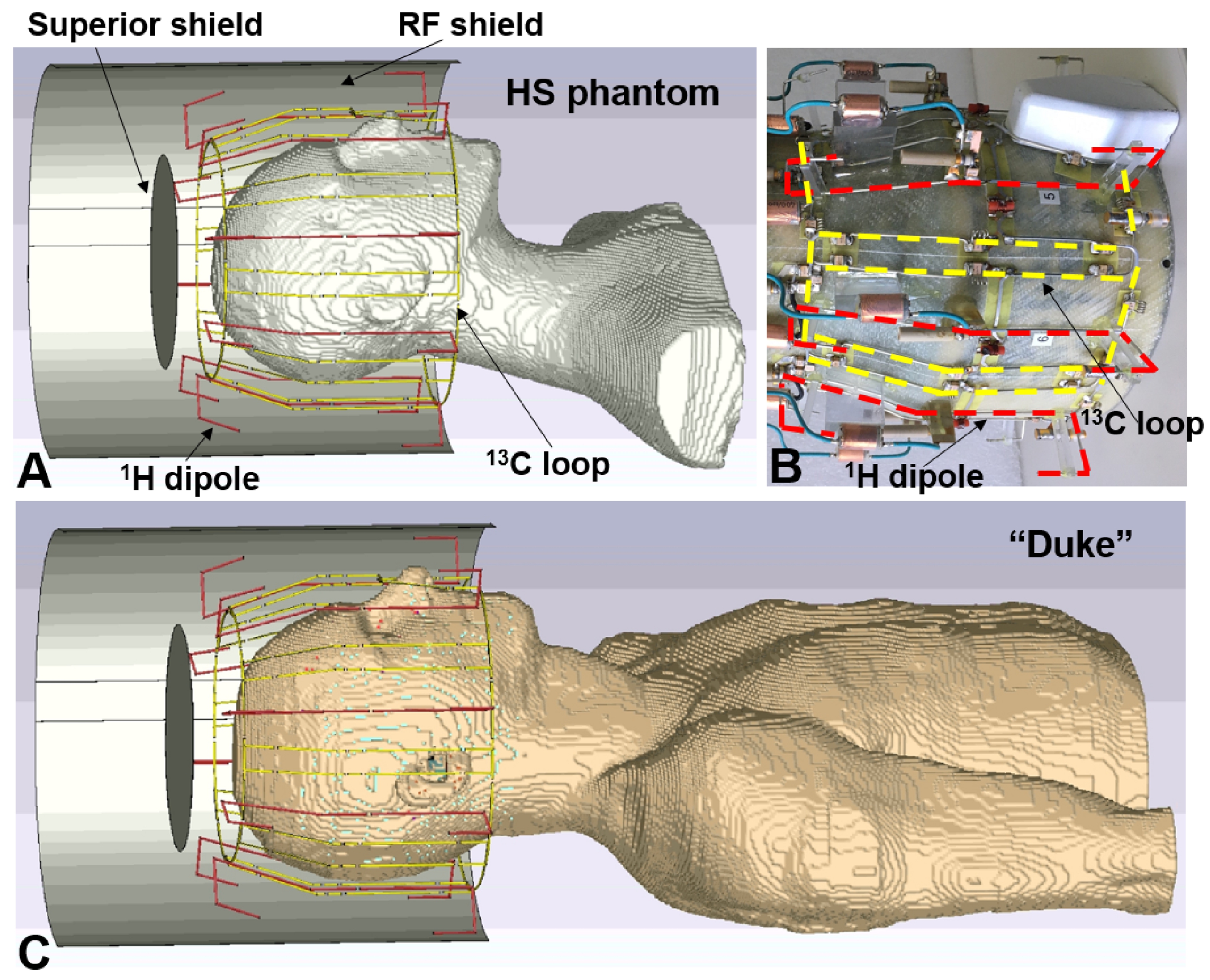
Figure 1. A) EM simulation model of
the double-tuned 13C/ 1H array coil loaded by the HS
phantom. B) Photo of the 13C/ 1H array with the RF shield
removed for better visualization. C) EM simulation model of the 13C/
1H array loaded by the Duke voxel model. In Figure 1B, dipoles and
loops are marked by red and yellow dashed lines, respectively.
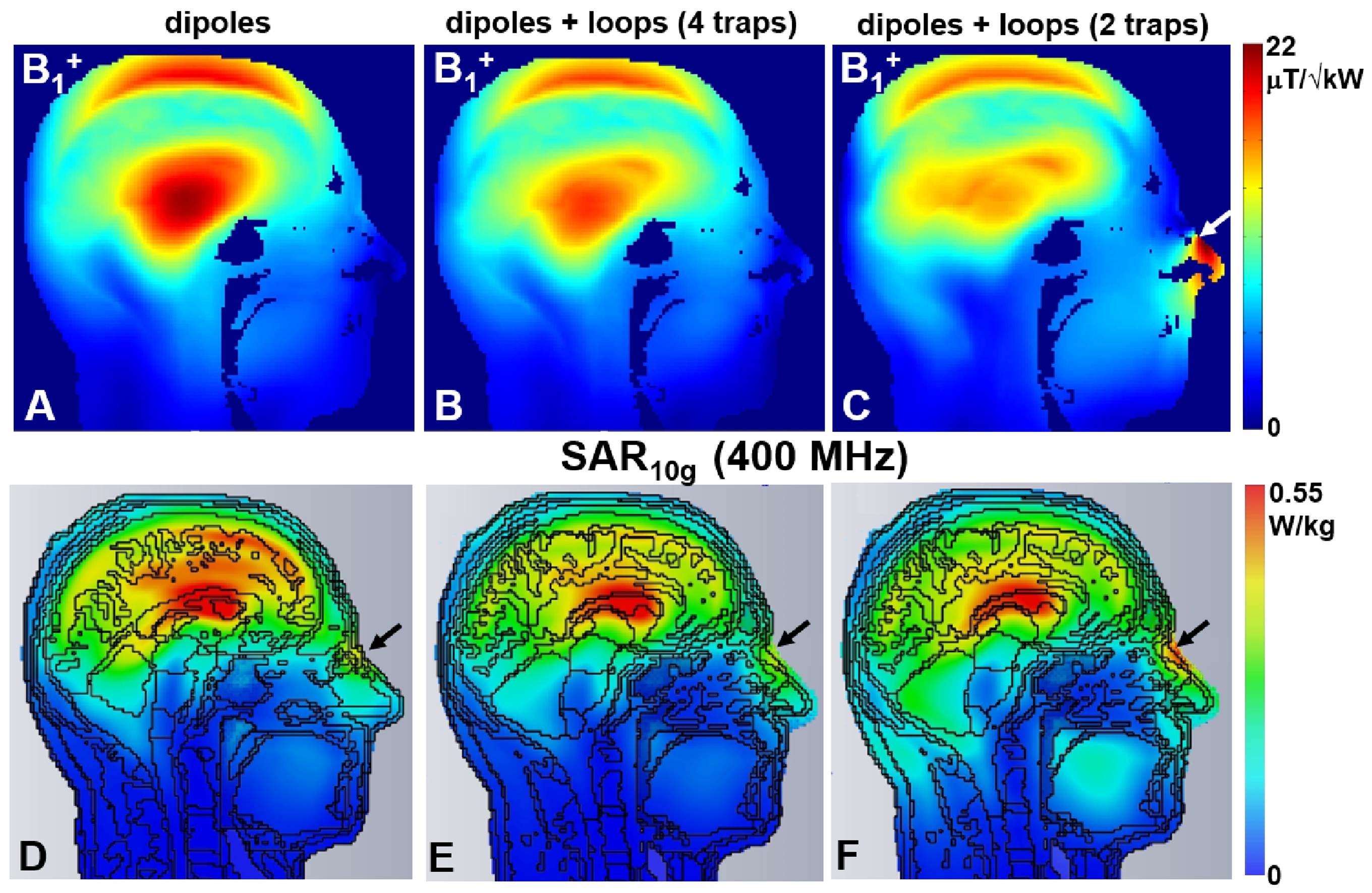
Figure 2. A) Central sagittal simulated B1+
map obtained using 8-element 1H dipole array without 13C loops. Central sagittal simulated B1+
maps obtained using 8-element 1H dipole array combined with 13C loops and different number of 1H traps introduced along the loop
length, i.e. 4 traps (B) and 2 traps (C). Central sagittal simulated SAR10g
maps obtained at 400 MHz using eight dipoles (D) and the presented DT 13C/1H array with different number of 1H traps, i.e. 4
(E) and 2 (F), introduced along the 13C loop
length. Black arrows show increase of SAR10g value for the model
with two 1H traps.
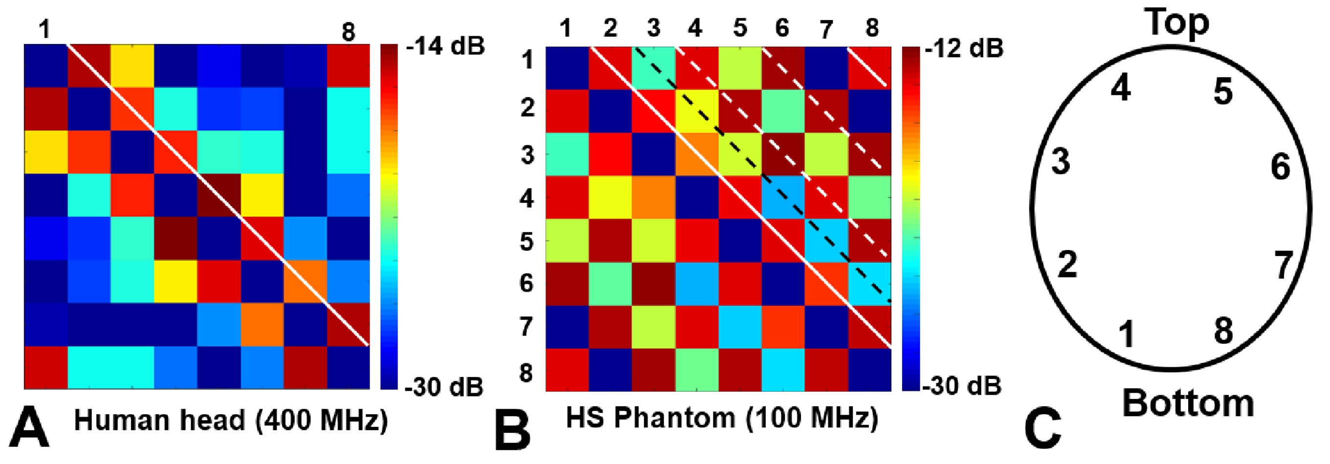
Figure
3. 8x8 S12 matrices obtained using the double-tuned 13C/ 1H array loaded by a human
head at 400 MHz (A) and by the HS phantom at 100 MHz (B). C) Numeration of the
coil elements.
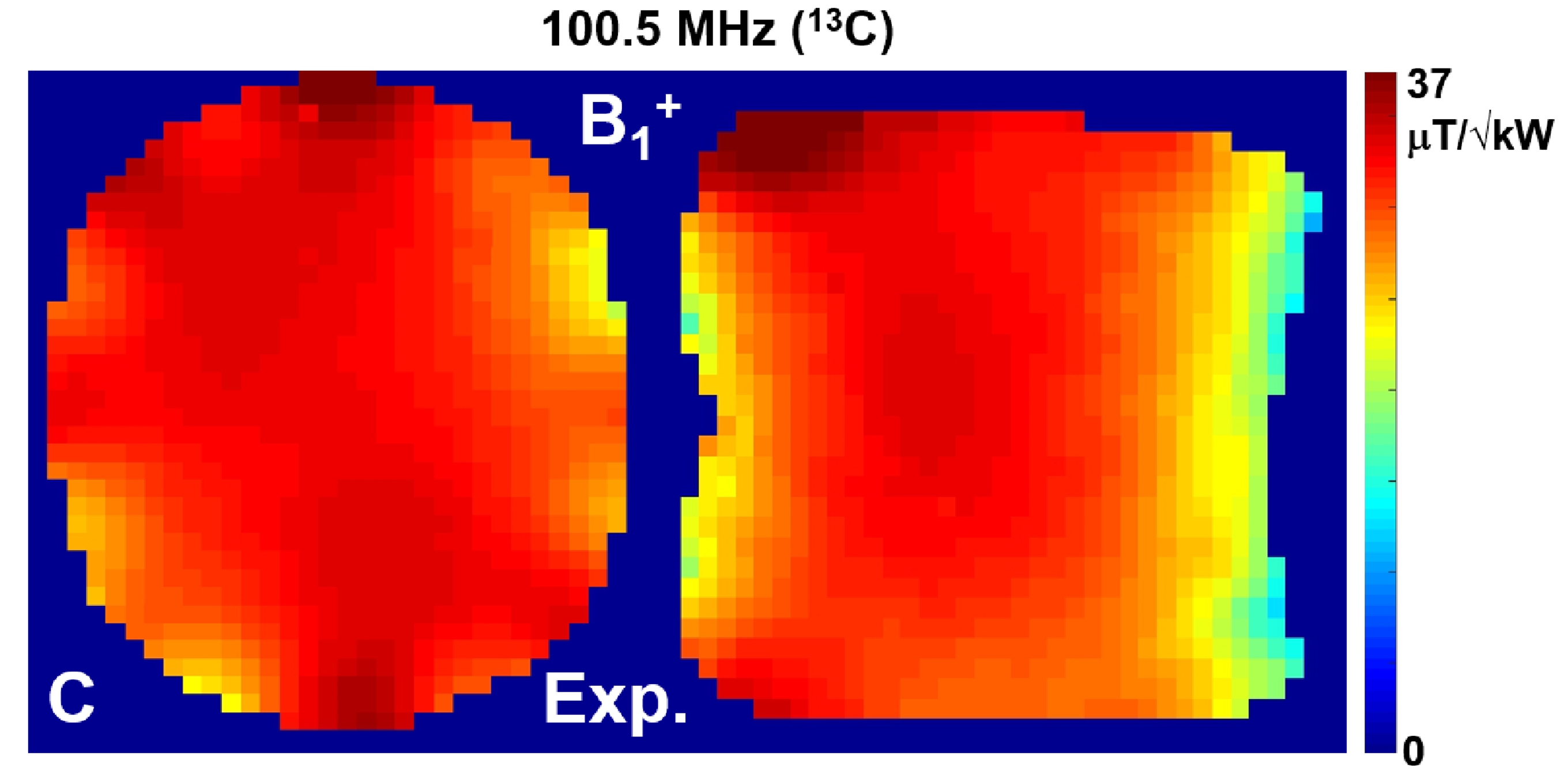
Figure
4. A) Experimentally measured 13C (100.5 MHz) central
transversal and sagittal B1+
maps obtained using the double-tuned 13C/
1H array loaded by the elliptical phantom filled with ethylene
glycol.
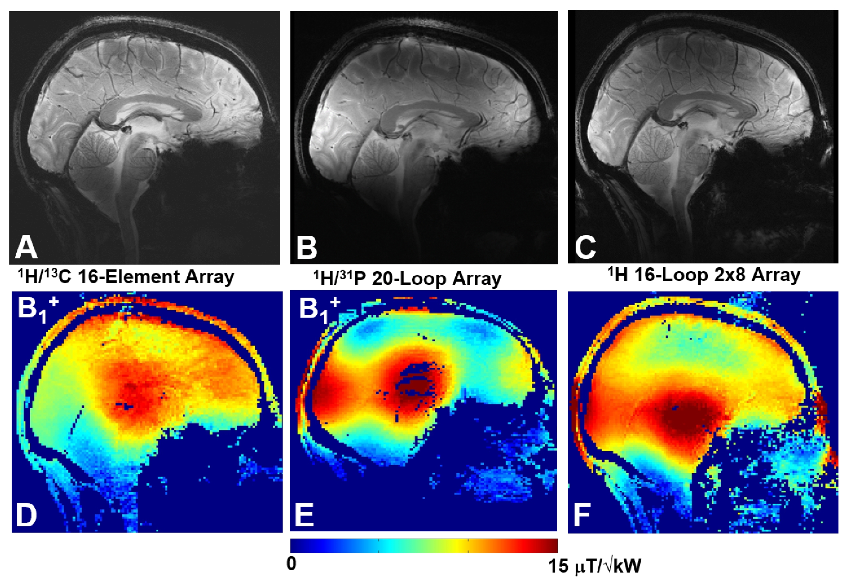
Figure 5. Central sagittal in-vivo human
brain GRE images (A, B, C) and corresponding B1+ maps (D, E, F) obtained using the presented double-tuned 13C/ 1H array (A,D), double-tuned
20-loop 31P/ 1H array (B, E), and single-tuned 16-loop
double-row 1H array (C, F).