2498
Ultra-Flexible 8-Channel Receive Array for 13C Imaging1Technical University of Denmark, Kgs. Lyngby, Denmark
Synopsis
Imaging of low-abundance nuclei could benefit from close proximity detecting coils. Close proximity is conveniently achieved using flexible arrays, which conform to the shape of the subject. In this work, a design of an 8-element ultra-flexible array for 13C imaging is presented. Each array element includes a low-noise preamplifier with 13C/1H active and passive decoupling, as well as high-power pulse protection circuits. The array is lightweight and easy to handle. The design approach is directly scalable to larger size arrays.
Introduction
Imaging of 13C isotope requires high sensitivity detector arrays. One way to increase sensitivity is to implement close proximity receiver arrays. To achieve close distance to a patient, the array shape should conform to the shape of the body, which is conveniently achieved by ultra-flexible coils. Ultra-flexible arrays can adopt to various patient sizes as well as different body parts 1. In order to keep the high detection performance, which is particularly important in imaging of low-abundance nuclei, a low-noise amplification circuitry may be co-integrated with the coil. In order to support flexibility of the coil and overall handling convenience, this circuitry must have a compact size, lightweight, and compatible with MR environment, which is challenging to attain.Methods
To fulfill the requirements outlined above, a compact, ultra-low noise preamplifier with integrated high-power pulse protection, active and passive decoupling circuitry is implemented. The size of this preamplifier circuit is 16mm x 19mm x 5mm. It is based on 3-element matching and decoupling network 2, 3, which, matches the coil to the optimal noise impedance of the active device4, Zn,opt, and, at the same time, provides maximum available impedance 2 Zo at the input terminals of the coil realizing preamplifier decoupling. The schematic representation of the single array element is shown in Fig.1.The coil loop is made of a flexible conducting material and in this case is based on 1 mm outer diameter coaxial cable. Only the outer conductor of the coaxial cable is used here. The diameter of the loop is 8 cm, which is chosen out of imaging considerations1. To avoid interaction with 1H coils of the scanner, a parallel resonator is integrated in the loop, as shown in Fig. 1. The resonator consists of lumped LC components and is tuned to block 1H current at 127.8 MHz. The effect of this blocking resonator is visible when measuring decoupling with a double-loop probe. The results of the measurements are shown in Fig. 2.
The resulting input impedance of the sample loaded loop coil is Zc ≈ 1 + j56 Ω at 32.1 MHz, which is a resonance frequency of 13C nuclei in 3T GE scanners. This impedance together with parameters of the amplifier, Zn,opt, Za (amplifier input impedance) are used in the design of the matching and decoupling network. The design is based on equations derived by Wang2 , which offer four alternative solutions. The equations can be used to design high impedance Zo as well as low impedance preamplifiers. Out of four possible solutions, the one shown in Fig. 1 is chosen here for practical reasons. The circuit is a T-network and consists of a 560 pF series capacitor, 112 pF parallel capacitor, and 2.7 uH series inductor (ceramic core 1812CS from Coilcraft). The total noise figure of the preamplifier including this matching and decoupling network is ≈ 0.6 dB. The resulting impedance of the preamplifier at the terminals of the coil is shown in Fig. 3. As can be seen, the preamplifier is noise matched when directly connected to the coil and, at the same time, presents high impedance to the input terminals of the loop. The measured passive decoupling is shown in Fig. 2. The circuit provides a local minimum in the double-loop probe measurements at the 13C resonance frequency. This indicates that influence of the coil on impedance of other elements in the array will be minimized.
Results
The designed coil is used as an element in an 8-channel array. The photograph of the array with cover removed is shown in Fig. 4(a).The preamp circuit size is a small fraction of the array, which supports the principle of flexibility. The circuit is connected to the scanner through a coaxial line and power supply wires. To minimize noise coupling between the channels, the coils are critically overlapped. The critical overlapping is found empirically by measuring SNR as a function of distance between the coils. As one can see from the measurement results in Fig. 4(b), the critical overlapping appears close to 2 cm (25% of coil diameter), which is what typically expected from these types of loop coils. The array is easy to handle and is compatible with various parts of the human body. To test imaging properties of the array it was applied to a human head phantom1. The photograph of the imaging setup in the scanner is shown in Fig. 4(c). The results of imaging experiments are shown in Fig.5.
Discussion and Conclusion
The array shows a reasonable coverage of the object to image. As expected, a higher sensitivity is achieved at the surface, and lower sensitivity further in the depth, which follows the sensitivity profile of a loop coil. The array is flexible, lightweight and easy to handle due to flexibility of the implemented wires and compact preamplifier design with integrated noise matching as well as passive and active decoupling circuits. The design is easily scalable and is potentially useful for realizing large arrays preserving flexibility, sensitivity and patient conformity.Acknowledgements
The authors would like to thank Danish National Research Foundation (grant DNRF124) for partial support of the activities.References
1. Juan Diego Sanchez-Heredia, Wenjun Wang, Rie B. Olin, Vitaliy Zhurbenko, and Jan Henrik Ardenkjær-Larsen, Enhanced Low Frequency MRI using Flexible Shape Arrays Made of Standard Wire, Proceedings of 14th European Conference on Antennas and Propagation. IEEE, 2020, 4 p.
2. Wenjun Wang, Vitaliy Zhurbenko, Juan Diego Sanchez Heredia, Jan Henrik Ardenkjær-Larsen. Three-element matching networks for receive-only MRI coil decoupling. Magn. Reson. in Med., Volume85, Issue1, January 2021, Pages 544-550. (published online: 19 July 2020)
3. Wenjun Wang, Vitaliy Zhurbenko, Juan Diego Sanchez Heredia, Jan Henrik Ardenkjær-Larsen. Matching and decoupling networks for receive-only MRI arrays. Proceedings of 14th European Conference on Antennas and Propagation. IEEE, 2020, 4 p.
4. LNA
for MRI, elcry1-u datasheet. Available online: elcry.com.
Figures
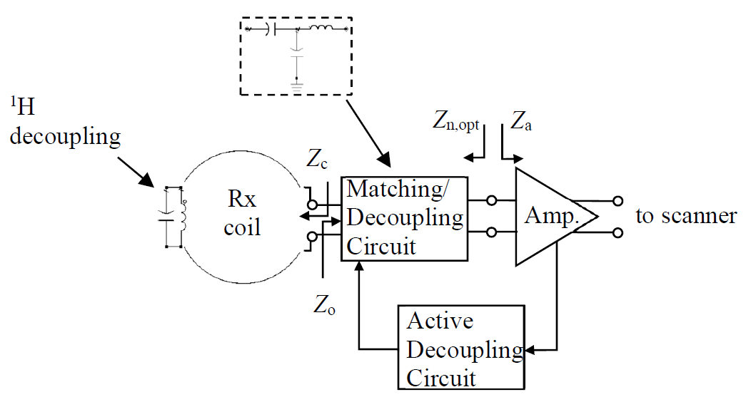
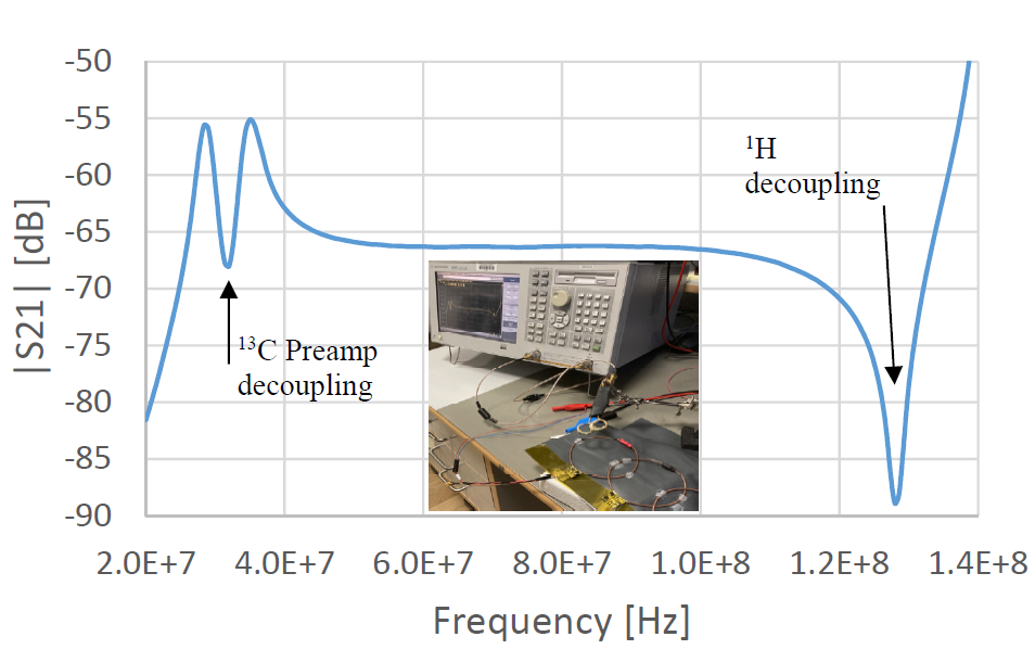
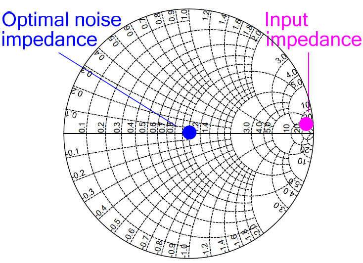
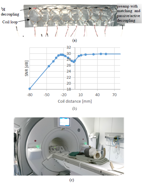
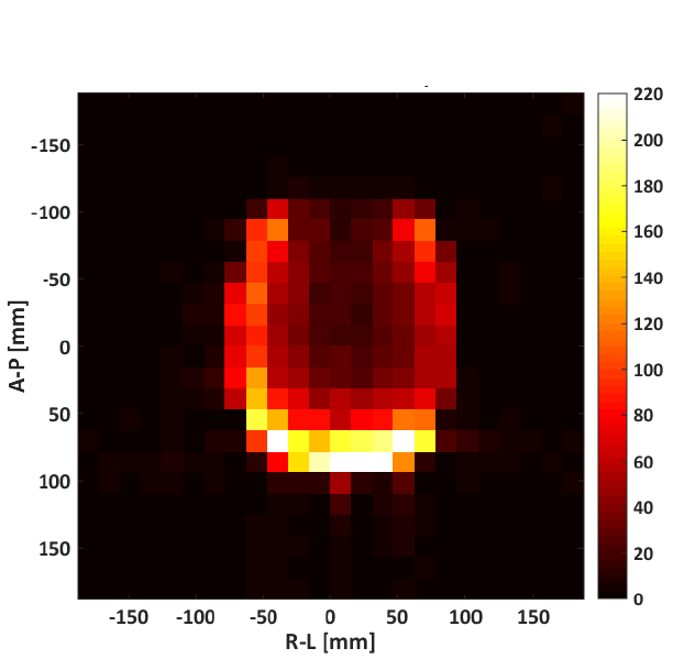
Fig. 5. SNR map for 8 channel array in Fig.4. Cross-section through the phantom perpendicular to the plane of the loop: Anterior-Posterior (A-P) and Right-Left (R-L) axis.
It should be noted that the array length is ~50cm while phantom head perimeter is ~60cm meaning that the phantom could not be covered entirely. This is the reason for a dark area on top of the image, where there is no active element.