2496
LCCC Balun for RF Coil1Vanderbilt University Institute of Imaging Science, Nashville, TN, United States, 2Department of Radiology and Radilogical Science, Vanderbilt University Medical Center, Nashville, TN, United States
Synopsis
We introduced a novel LCCC lumped-element balun to suppress the unwanted common-mode current in RF coils and RF systems. Unlike the 4-element Lattice balun consisting of two capacitors and two inductors (LCCL), this design has 3 capacitors and only 1 inductor. With fewer inductors (previous lumped-element baluns need at least 2 inductors), this LCCC balun can further be miniaturized and has lower insertion loss.
Purpose:
Baluns are commonly used to connect an RF coil (a balanced device) to a coaxial cable (an unbalanced device). Seveal baluns or similar circuits have been proposed and applied in MRI coil designs, including the cable trap, float balun, and the lattice balun1-3. Among these methods, the lattice balun is one widely-used technology with RF coils because it can be built directly on the coils’ feed board and has a relatively small footprint. The lattice topology commonly uses lumped-element lowpass/high-pass networks to split the signal at the unbalanced port into two signals at balanced ports that are equal in power but with a 180° phase difference. In this case, it can suppress the unwanted common-mode current and has little effect on the desired differential-mode signal. For the lattice balun with the lowest number of components, it requires two inductors and two capacitors: one series capacitor and one parallel inductor for the low-pass, and one series inductor and one parallel inductor for high-pass networks. In MRI application, non-magnetic capacitors typically are smaller and have lower losses (i.e., higher quality factors) compared to non-magnetic inductors. Therefore, reducing the number of inductors will benefit miniaturization and reduce circuit losses. We developed an asymmetrical 4-element balun circuit for MRI coil applications. Unlike the 4-element Lattice balun consisting of two capacitors and two inductors (LCCL), this design has 3 capacitors and only 1 inductor, referred to as an LCCC balun.Methods:
Concept:Fig. 1 shows the diagram of a Lattice balun with 2 inductors and 2 capacitors and the proposed LCCC balun with 3 capacitors and only 1 inductor. To be a well-matched and lossless balun circuit, the following three criteria must be met:
1). Mag (S12) = Mag (S13) = -3 dB; equal split.
2). Abs (Phase (S12) - Phase (S13)) = 180 degrees, opposite phase.
3). S11 = S22 = S33 =0, impedance matching.
The values of these lumped elements can be derived by calculating the ABCD transform matrix and Scattering parameter matrix, as shown in Figure 2.
Circuit Simulations:
Two LCCC baluns (one for 3T 128 MHz and one for 7T 298MHz) were simulated using the Ansys EM package (Canonsburg, PA, USA). The calculated capacitance and inductance for 7T and 3T are Lmid = 62.1699 nH, Cmid = Ctop = 2Cbot = 49.7359 pF and Lmid = 26.7038 nH, Cmid = Ctop = 2Cbot = 21.3631 pF, respectively.
Fabrication and Evaluation:
A 3T LCCC balun was fabricated and evaluated. We measured the insertion loss and common-mode rejection ratio (CMRR). The insertion loss was measured as the S21 between the unbalanced terminal and the balanced terminal. The CMRR was measured with two current probes electromagnetically coupled to the input and output coax shields.
Results:
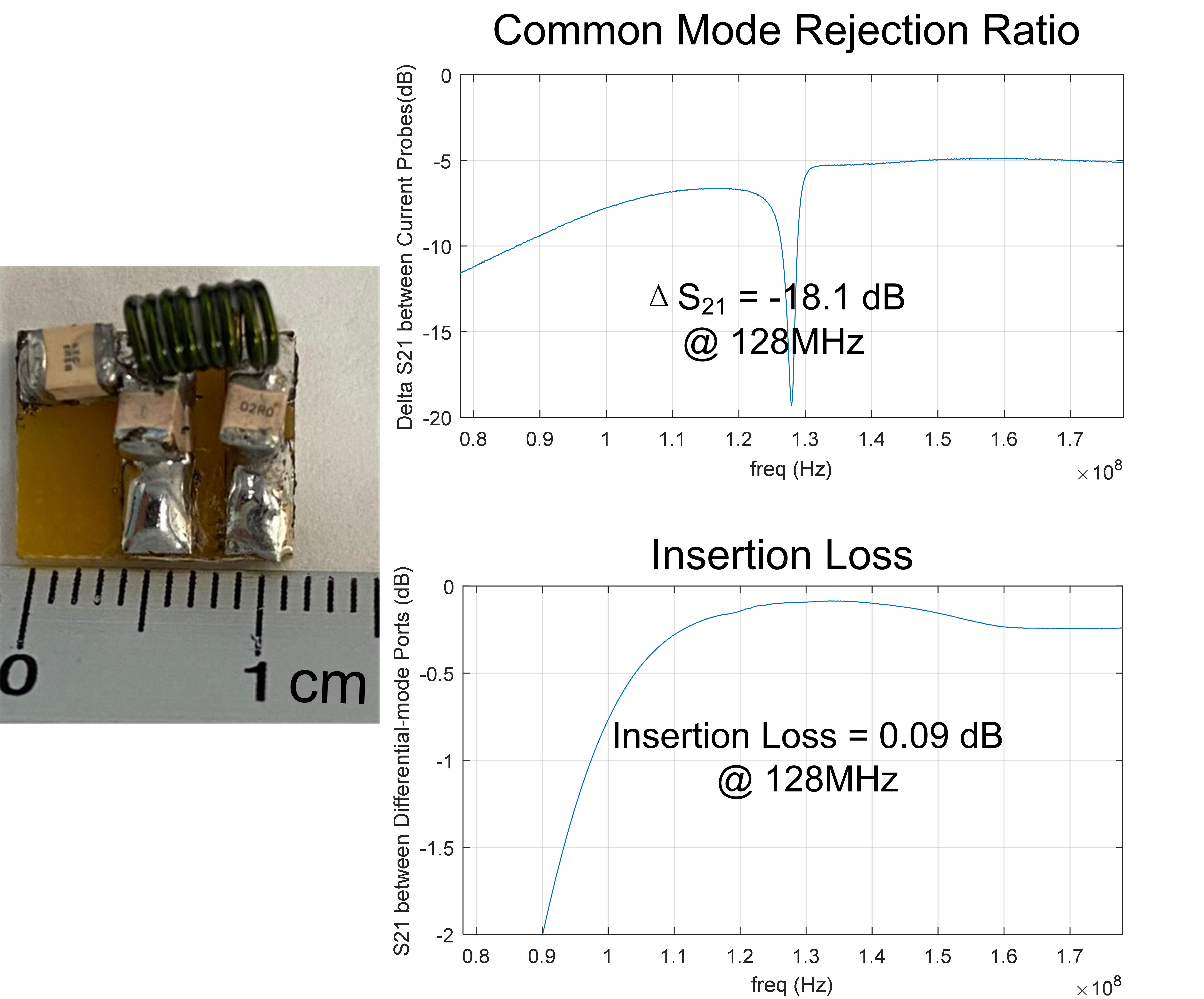
Figs 3a and 4a show the simulated S21 plots between the unbalanced port and two balanced ports. The output signals of two balanced terminals had an equal magnitude (both -3 dB) and were out of phase (+90 and -90) at the desired frequencies (128MHz and 298 MHz). This is consistent with the theoretical analysis and can suppress the common-mode signal. Figs 3b-c and 4b-c show simulated CMRR and insertion loss of these LCCC baluns. For ideal cases (as set up in simulation), CMRR can achieve an infinite value and the insertion loss can be zero. This indicates the LCCC balun is theoretically a lossless circuit even though circuits in two output branches are not symmetrical.Figure 5 shows the fabricated 3T LCCC balun (dimension 1.1× 0.6 mm2) and the bench test results. The measured insertion loss is only 0.09 dB and CMRR can achieve 18.1 dB, which means up to 98.5 % common-mode power was removed.
Conclusion:
We introduced a novel LCCC lumped-element balun with 3 capacitors and only 1 inductor. With fewer inductors, this LCCC balun can be further miniaturized and has a lower insertion loss than previous designs.Acknowledgements
This work was supported by NIH R21 EB029639.References
1. Peterson, D. M., Beck, B. L., Duensing, G. R., & Fitzsimmons, J. R. (2003). Common mode signal rejection methods for MRI: reduction of cable shield currents for high static magnetic field systems. Concepts in Magnetic Resonance Part B: Magnetic Resonance Engineering: An Educational Journal, 19(1), 1-8.
2. Harrison, W. H., Arakawa, M., & McCarten, B. M. (1987). U.S. Patent No. 4,682,125. Washington, DC: U.S. Patent and Trademark Office.
3. Yang, X., Zheng, T., & Fujita, H. (2006, May). T/R switches baluns and detuning elements in MRI RF coils. In ISMRM Fourteenth Scientific Meeting Weekend Syllabus.
4. Terman FE. 1947. Radio engineering. New York: McGraw-Hill; 690 p
5. C.LORENZ AG Berlin-Tempelhof, “Schaltungsanordnunk zum Ubergang von einer symmetrischen, lektrischen Anordnung zu einer unsymmetrischen, insbesondere bei Hochfrequenzanwendungen,” German Patent, , no. 603816, April 1932
Figures