2495
Advances in Caterpillar Traps: A Highly Flexible, Distributed System of Toroid Cable Traps
Ekin Karasan1, Alison Hammerschmidt1, Victor Taracila2, Fraser Robb2, and Michael Lustig1
1University of California, Berkeley, CA, United States, 2GE Healthcare, Coils, Aurora, OH, United States
1University of California, Berkeley, CA, United States, 2GE Healthcare, Coils, Aurora, OH, United States
Synopsis
Conducting wires within the scanner may interact with the transmit field causing high shield currents and posing safety hazards. Closely spaced RF traps are used to mitigate common-mode currents. However, these bulky and rigid traps hinder the flexibility of the cable. We previously proposed caterpillar traps: a distributed system of smaller, flexible toroids covering the full length of the cable. Their potential to attenuate shield currents while being flexed was demonstrated. This work makes several improvements to the manufacturing process to reduce time and cost and improve usability. Furthermore, we present results from experiments to evaluate their performance and robustness.
Introduction
Common-mode currents can occur on the shield of coaxial transmission lines between RF coils and the main system, causing B1-field inhomogeneities and posing risk of RF burns to the subject [1]. To attenuate these currents, a few high blocking, resonant cable traps are placed along the cable. They work by either inductively coupling or directly connecting to the shield current [2,3,4]. These high-Q resonant traps must be rigid to prevent geometry changes, hindering the flexibility of the cable. Moreover, the placement of traps must be optimized for maximum performance. Previously, we proposed caterpillar traps [5], a distributed design of cable traps that replace conventional traps with smaller, flexible, self-shielded toroids that inductively couple to the shield current (Figure 1). Resonant toroids can be placed along the full length of the cable, separated by spacers. We demonstrated that caterpillar traps can be flexed while still providing sufficient attenuation.Here, we propose several advancements in the manufacturing process. Previously, toroids were tuned using four surface mount capacitors in series. To reduce manufacturing cost and time, we replace this with a distributed capacitance through a twisted pair transmission line that can be easily tuned by making cuts. In addition, a clamp-on version of the toroids was developed for easier assembly. The performance of the traps was further confirmed with B1 distortion and heating measurements.
Methods
Fabrication:The resonant toroids and spacers are manufactured on a low-loss Polydimethylsiloxane (PDMS) substrate. A toroidal injection molding die was designed with slits for wires. A stiff substrate was chosen for resonant toroids (45 Shore-A) and a more flexible substrate was chosen for spacers (20 Shore-A). To create a distributed capacitance through a twisted pair transmission line, we twist two 28 AWG, low-loss Polytetrafluoroethylene (PTFE) coated wires with a hand drill. The twisted wires are wound on the toroid. For tuning, six cuts are made at certain points, creating four smaller capacitors in series (Figure 2a-b). A residual open wire forms a parallel capacitance that can be twisted for fine tuning.
For the clamp-on version, a cable tie was molded inside the toroid and used to open and close it (Figure 2d). To not alter the electrical connection during this process, a connection was made through the inside by soldering to another wire, instead of across the opening.
Benchtop:
Benchtop experiments were conducted to compare the performance of different capacitor designs. Five toroids were constructed with each design: 1) Fixed capacitors, 2) Fixed and variable capacitors, 3) Closed, and 4) Clamp-on twisted pair capacitance. Toroids were fit on a 10.5mm diameter copper rod with spacers on two sides, and the attenuation was measured with the setup in Figure 3a-b. The clamp-on toroids were then tested for consistency by clamping on and removing each from the rod five times and measuring resonance frequency and attenuation.
Scans:
B1-mapping and heating experiments were performed on a 3T GE MR750W system (Waukesha, Wisconsin). Two copper rods were cut to the length of a 127.7MHz resonant dipole (~1.2m) and bent (Figure 4). One was equipped with 57 resonant toroids with twisted pair capacitance, separated by equally-sized spacers, while the other was equipped only with spacers. B1-mapping measurements [6] were made with a target flip angle of 30 degrees on two non-loading phantoms. Initially, a B1 map of a slice 1cm below the top of the phantoms was measured (Figure 4a). Then, the rods were successively placed on the phantoms and a B1-map was acquired at each configuration (Figure 4b-c). To evaluate their robustness to applied pressure, a smaller non-loading phantom and a larger loading phantom were placed as weights on the rod with traps, and a B1-map was measured with each (Figure 4f-g).
Afterwards, the rod equipped with traps was placed near the top of the bore and a 15 minute heating test was performed (Figure 5). A heat map was measured immediately after. The rod was rotated in 90 degree increments and a measurement was made at each of the four orientations.
Results and Discussion
The attenuation provided by different capacitor designs were similar (Figure 3c). The fixed capacitors performed the best followed by the closed twisted pair design, the variable capacitor design and the clamp-on design. The results of the consistency measurements for the clamp-on design are summarized in Figure 3d. We observed very small deviations in resonance frequency and attenuation. The maximum deviation from mean resonance was 0.28MHz.The results, in degrees, of the B1 distortion experiments are shown in Figure 4. Overall, putting pressure on the traps had minimal effect on the B1-maps (Figure 4f-g). Finally, results of the heating tests are shown in Figure 5. The RF interaction with the body coil depends on the geometry and placement with respect to the coil, resulting in different current distributions for different orientations. While the performance of conventional designs can depend on the locations of traps, our distributed design guarantees the existence of RF blocking for every orientation.
Conclusions
Caterpillar traps are a distributed design of cable traps that can provide sufficient attenuation to shield currents while enabling flexing. This study makes improvements to the manufacturing process and reinforces their performance and robustness.Acknowledgements
We thank GE Healthcare for research support and funding support from the following NIH grants: U01EB025162, U01EB029427.References
- Beck BL, Peterson DM, Duensing GR, Fitzsimmons JR. 2000. Implications of Cable Shield Currents at 3.0 and 4.7 Tesla. Int Soc Magn Reson Med, Denver, CO. p 641.
- X. Yang and F. Fujita, “T/R switches, baluns, and detuning elements in MRI RF Coils,” Proc. Intl. Soc. Mag. Reson. Med. 14, Seattle, 2006.
- Seeber, D. A., J. Jevtic, and A. Menon. "Floating shield current suppression trap." Concepts in Magnetic Resonance Part B: Magnetic Resonance Engineering: An Educational Journal. (2004): 26-31.
- Burl, M., Chmielewski, T., & Braum, W. O. (2001). Patent No. US6593744B2.
- Karasan, E., Taracila, V., Robb, F., Lustig, M. “The Very RF Hungry Caterpillar Trap(Highly Flexible, Distributed System of Toroid Cable Traps),” Proc. Intl. Soc. Mag. Reson. Med. 29, Paris, 2020.
- Sacolick, Laura I et al. “B1 mapping by Bloch-Siegert shift.” Magnetic resonance in medicine vol. 63,5 (2010): 1315-22. doi:10.1002/mrm.22357
Figures
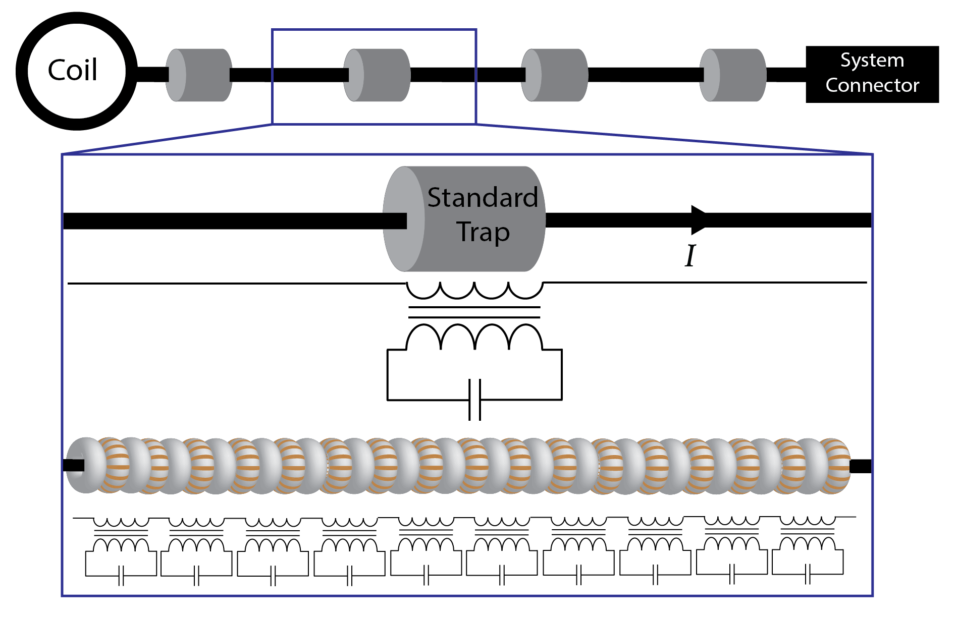
A few large floating
cable traps placed on a cable connecting an RF coil to the main system. A
portion of the cable is selected, comparing the standard floating trap design
to caterpillar traps. Standard floating traps inductively couple to the shield
current, $$$I$$$, and impose a large
impedance. In contrast, our distributed design of caterpillar traps consists of
smaller toroids each inductively coupling to the shield current. Although each toroid imposes a smaller impedance, by covering the full length of the
cable with these traps, shield currents can be sufficiently attenuated.
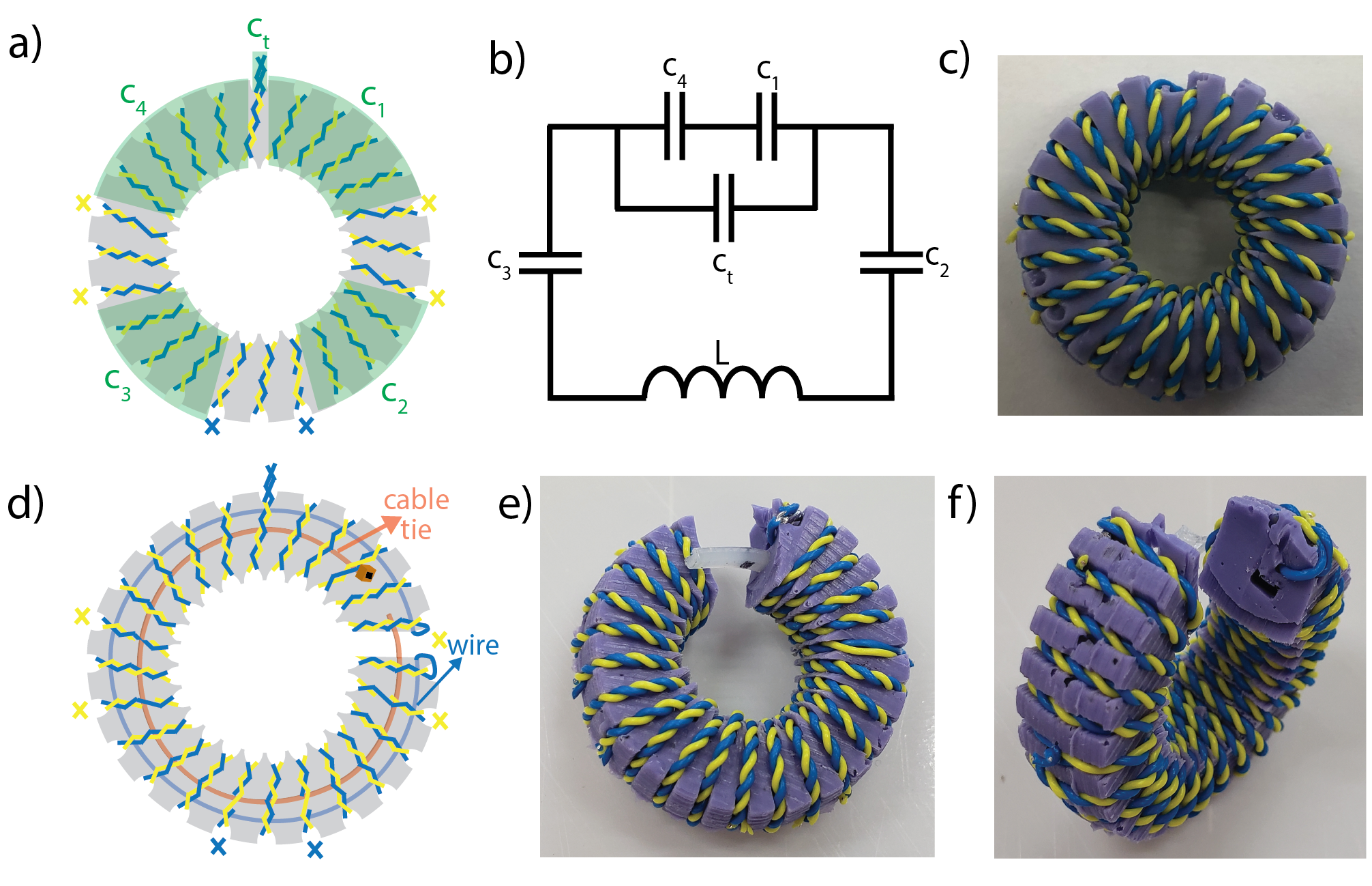
Closed and clamp-on
toroids built with a distributed twisted pair capacitance. a) A schematic of
the closed model. The two twisted wires are cut at points marked with crosses,
creating four capacitors in series. A residual open wire can be twisted to form
a tuning capacitor in parallel, $$$c_t$$$. b) Corresponding circuit diagram. c)
Manufactured toroid. d) A schematic of the clamp-on model. A cable tie is
molded inside to open and close the toroid. An electrical connection is made
through the inside of the toroid by soldering to an additional wire. e-f) The
clamp-on design from two angles.
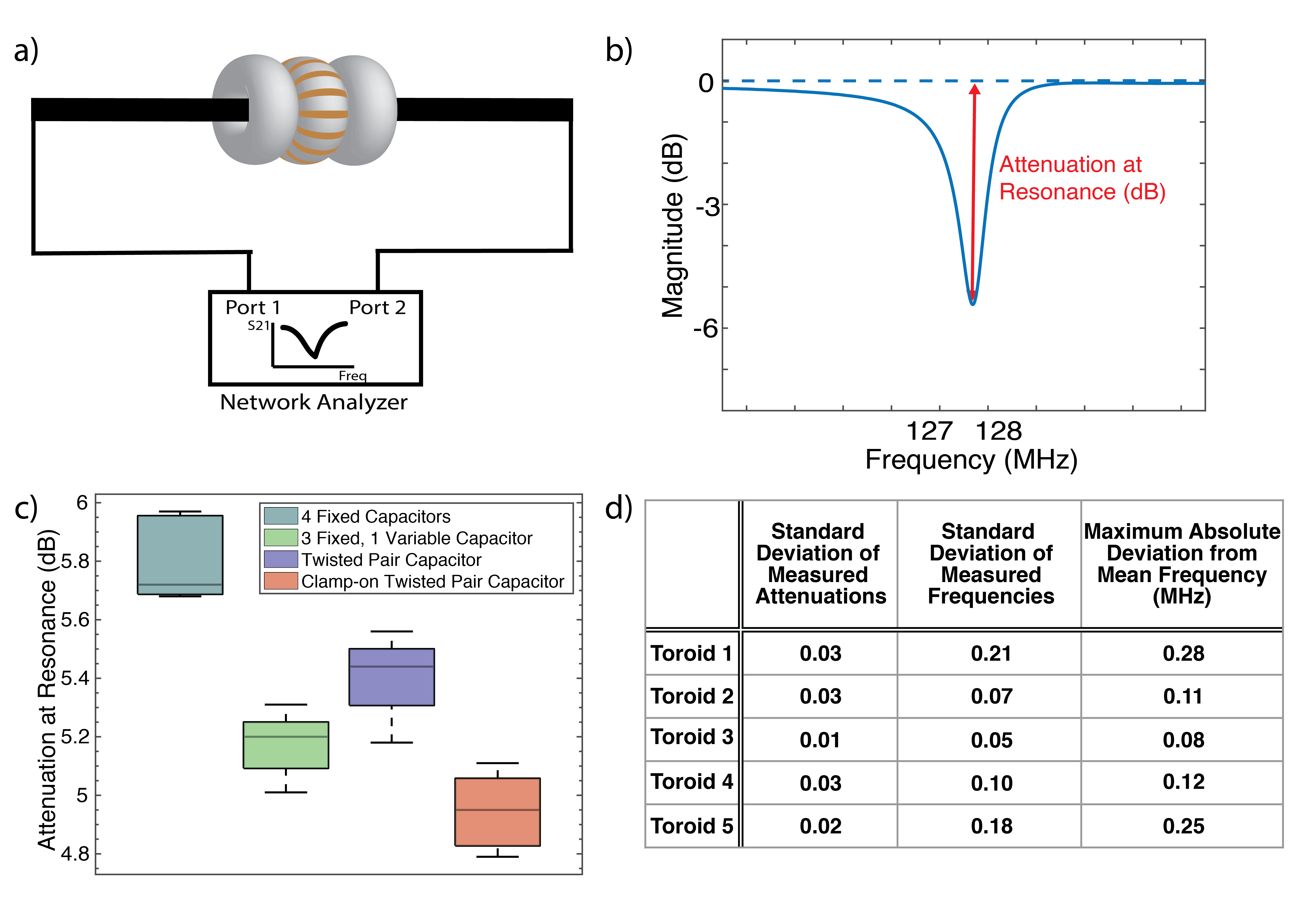
Benchtop measurements. Five toroids (ID=10.5mm,
OD=26.5mm)
were made for each model: 1) fixed capacitors (5.6pF), 2)
fixed (4.7pF) and variable capacitors (8-30pF), 3) closed and 4) clamp-on
twisted pair capacitor. a) A copper rod is connected to two ports of the
network analyzer. Each toroid is placed with spacers and tuned to
127.7±0.3MHz. Fixed capacitor design could not be fine tuned and had wider
range. b) S21 attenuation at resonance is measured. c) Attenuation results shown
in a box plot. d) Results from consistency measurements with clamp-on
toroids show very small deviation.
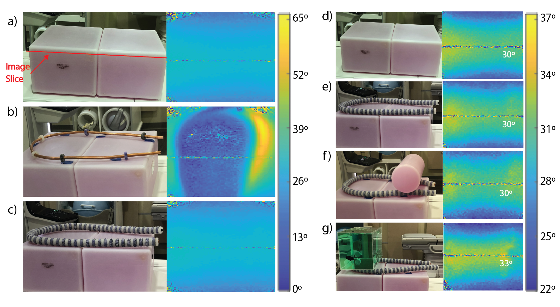
B1 mapping experiments. Initially, a B1 map with 30 degree
target flip angle of a slice 1cm below the top of phantoms is acquired with
three configurations and displayed in 0-65 degree range: a) phantom only,
conductor equipped with b) spacers only and c) caterpillar traps. d-e) Results
from a) and c), respectively, displayed in 22-37 degree range. To test the
performance under stress: f) a smaller non-loading phantom, g) a larger loading
phantom are placed as weight on the caterpillar traps and the maps are shown in
22-37 degree range. Putting weight on the traps has minimal effect.
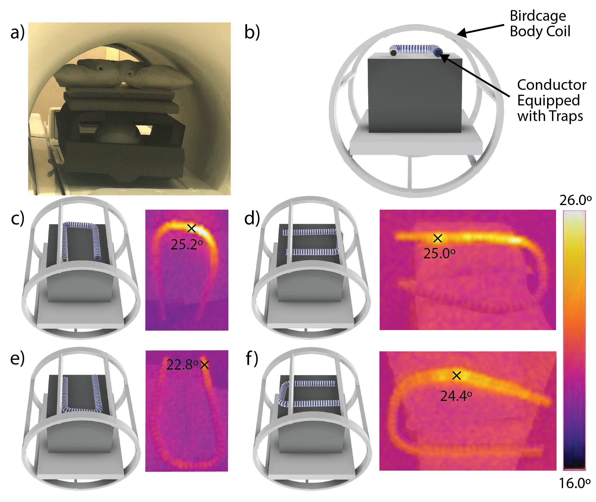
Heating Tests. a) The conductor equipped with
toroids is placed near the top of the bore. b) The corresponding schematic of
the setup. c-f) The rod was placed in four rotated configurations and a 15 minute
heating sequence was performed at each. A heat map was acquired immediately at
the end of the sequence. The rod is let to cool between tests. Minimal heating is observed at each orientation. The RF
interaction with the body coil depends on the geometry and placement relative
to the coil. The distributed design guarantees the existence of RF blocking for
every possible orientation.