2492
Realistic model of the 3T Siemens Connectom birdcage coil and its validation1Max Planck Institute for Human Cognitive and Brain Sciences, Leipzig, Germany, 2Felix Bloch Institute for Solid State Physics, Leipzig, Germany
Synopsis
We devised a numerical model of a 123.2MHz 32-rung high-pass whole-body birdcage coil of the Siemens 3T Connectom scanner. The model was developed based on realistic geometrical data for most of coil elements and a reverse engineering approach. Our simulations suggest that RF exposure at level of 3.2W/kg head SAR may result in higher than 20W/kg of SAR10g in the Connectom scanner; (ii) B1+ mapping alone cannot be used for validation of numerical model of whole-body birdcage coil, (iii) developed RF-circuit and 3D-EM co-simulation approach with reverse engineering resulted in a reasonable agreement between simulations and measurements in human subject.
Introduction
Whole-body birdcage coils are commonly used as radio-frequency (RF) transmitters of electromagnetic (EM) fields during clinical 1.5T and 3T MRI. To deliver the highest possible gradient field performance design of the 3T Siemens Connectom, the system’s birdcage coil was modified by reduction of the coil’s inner diameter and the distance between the coil and its shield. The head specific absorption rate (SAR), which is SAR averaged over the entire mass of the head and over 6 minutes time, limits (at the level of 3.2W/kg) the average level of RF exposure for a subject undergoing an MRI examination at the head landmark position1. However, when devices are located in the bore which modify the EM field generated by the birdcage coil (e.g. a clip-on magnetic field camera), and which were not considered in the design of the coil, the primary safety limit becomes local SAR averaged over 10 grams and 6 minutes time (SAR10g)1. The goals of this study were: (i) to develop a numerical model of the real RF coil using reverse engineering, (ii) to investigate variations of subject-specific SAR10g taking into account coil position inside the shield, and (iii) to compare numerical and experimental results for human subject experiment.Methods
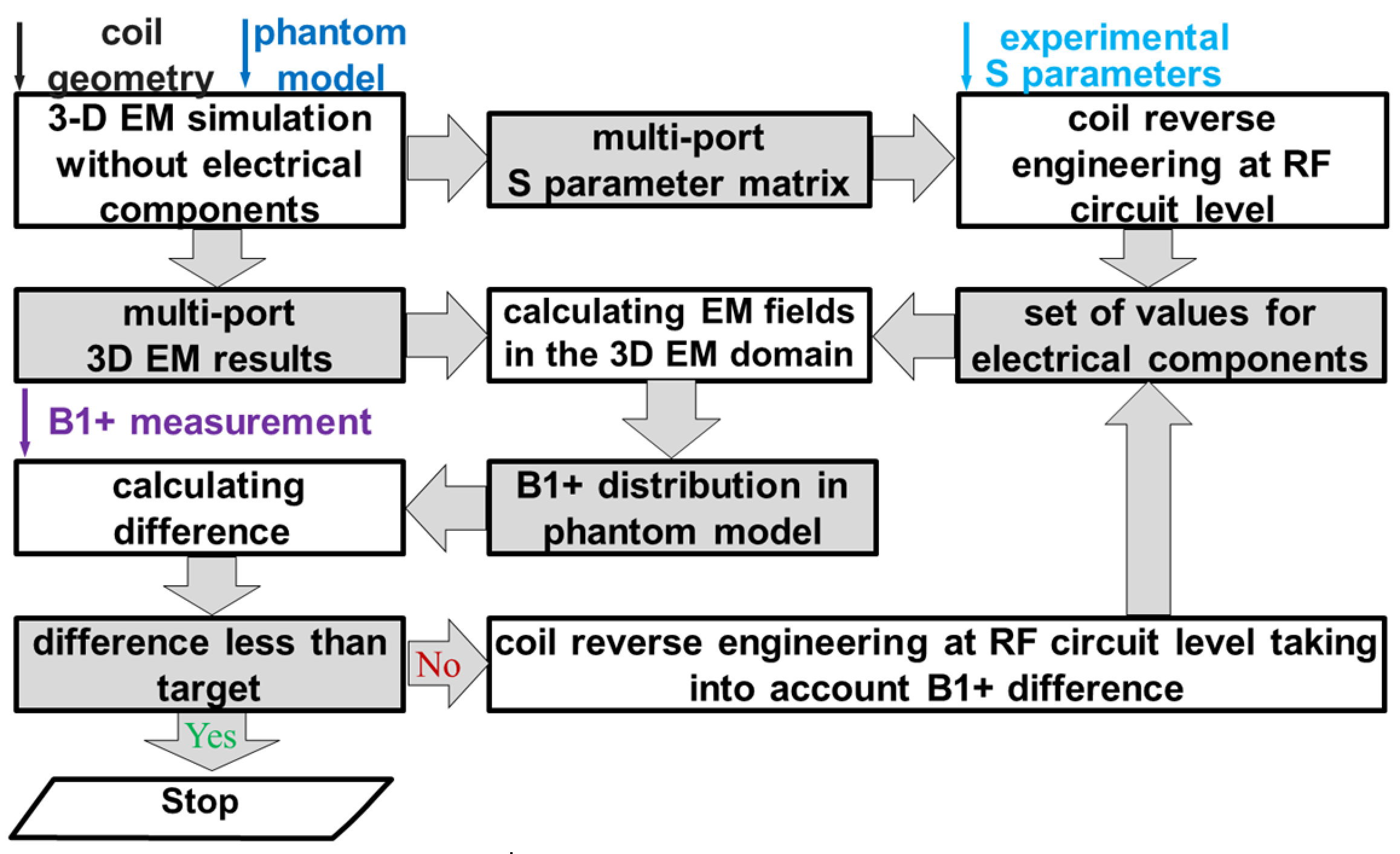
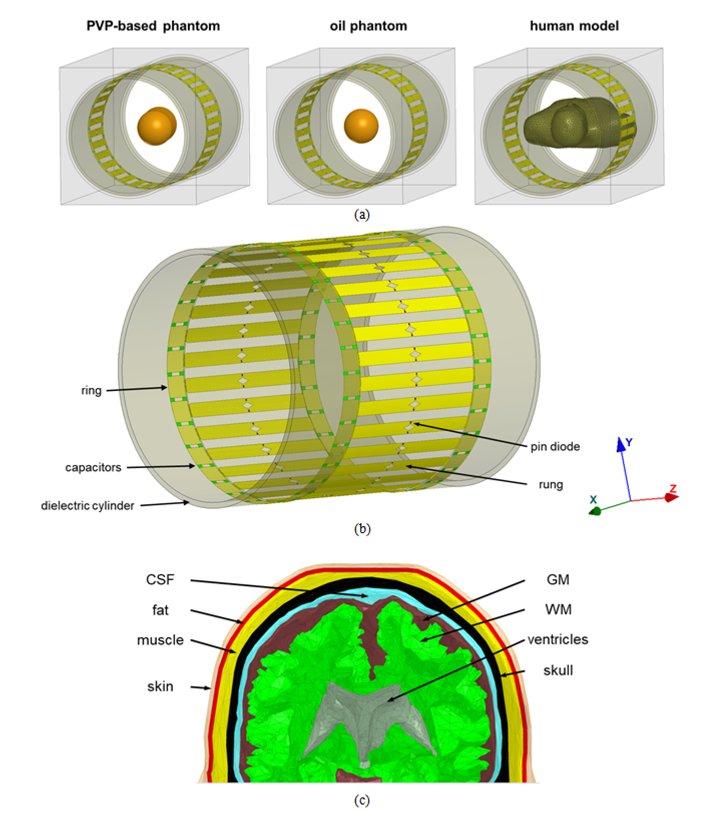
We applied reverse engineering approach (Fig. 1) to develop a numerical model of a 123.2 MHz 32-rung high-pass whole-body birdcage coil of the customized Siemens 3T Connectom scanner (Siemens Healthineers, Erlangen, Germany). The data sources of the reverse engineering were experimental measurements of: (i) coil S parameters, (ii) 3D B1+ maps obtained for given transmit power. They were obtained for oil and PVP-based phantoms (Fig. 2a). The coil model included inner dielectric cylinder, pin-diodes, that is used for coil detuning during RF reception, realistic geometries of rings and rungs, and realistic locations and dimension of the capacitors (Fig. 2b). Using the developed coil model, B1+, head SAR and SAR10g were evaluated for two high-resolution human head and torso models developed in previous work2,3 (Fig.2a,c) and located at head landmark position. Electrical properties of human tissues were taken from the IT’IS database4. Axial coil position inside the shield was varied in a range of ±1 mm for both axes.Experimental B1+ maps in a human subject were additionally obtained. All maps were acquired by the standard double angle method5. A gradient and RF spoiled 3D gradient echo sequence with 2 mm (phantoms), 2.5mm (in-vivo) isotropic resolutions was repeated twice for RF pulses with nominal flip angles 60°, 120°. A rectangular-shaped 0.5ms RF pulse was used for phantoms. A 2.56ms sinc-shaped RF pulse. For in-vivo TR was 20s and total imaging time 21 minutes per slice. In post-processing, the maps were corrected for gradient non-linearity.
Results and Discussion
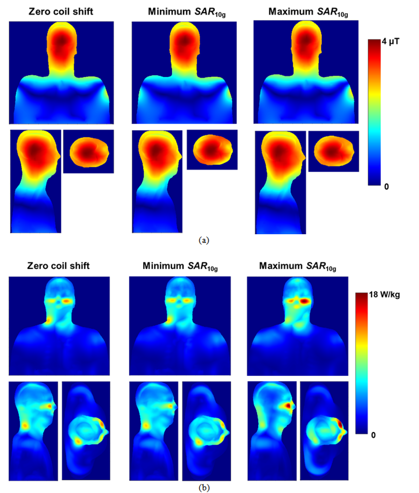
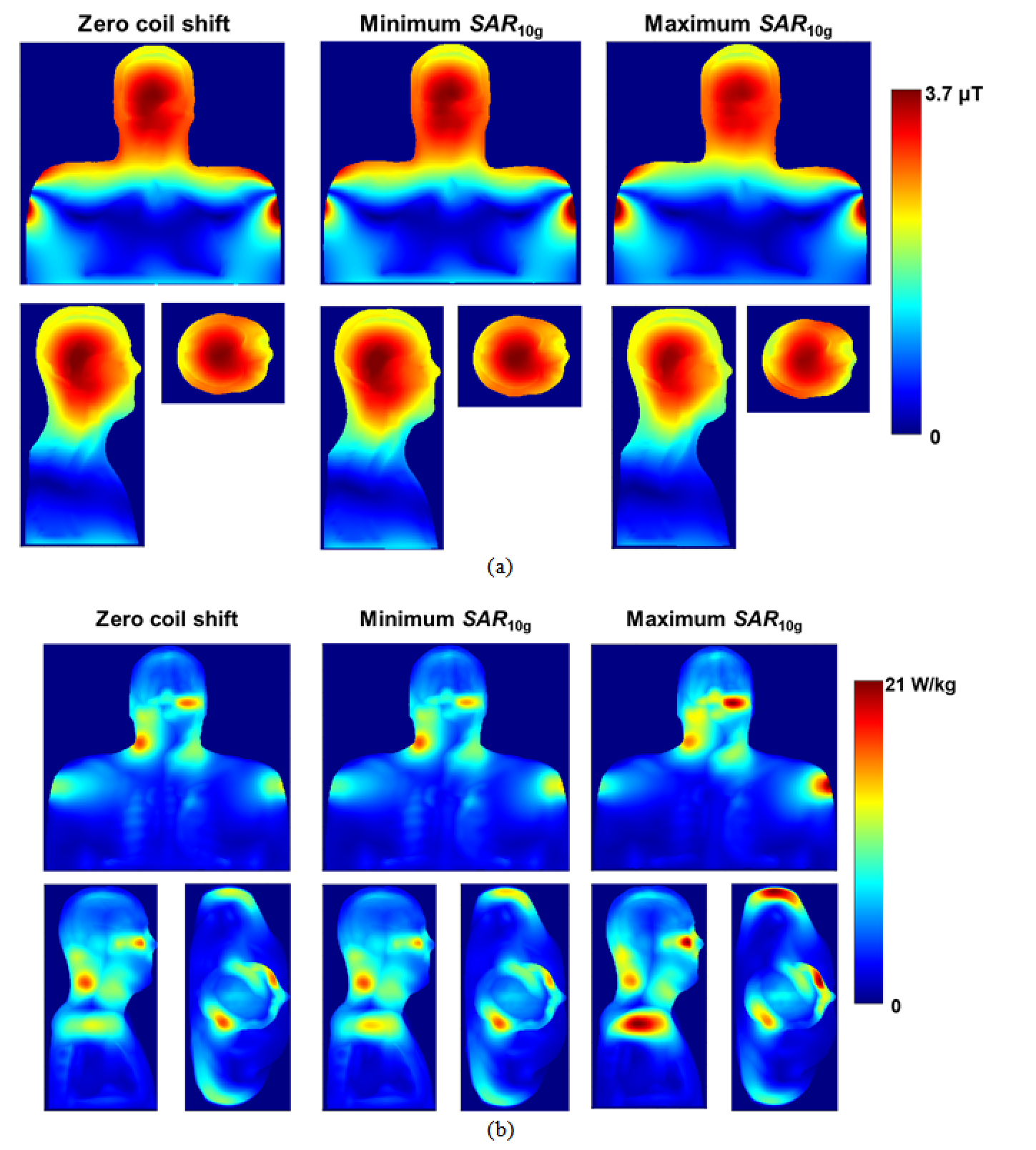
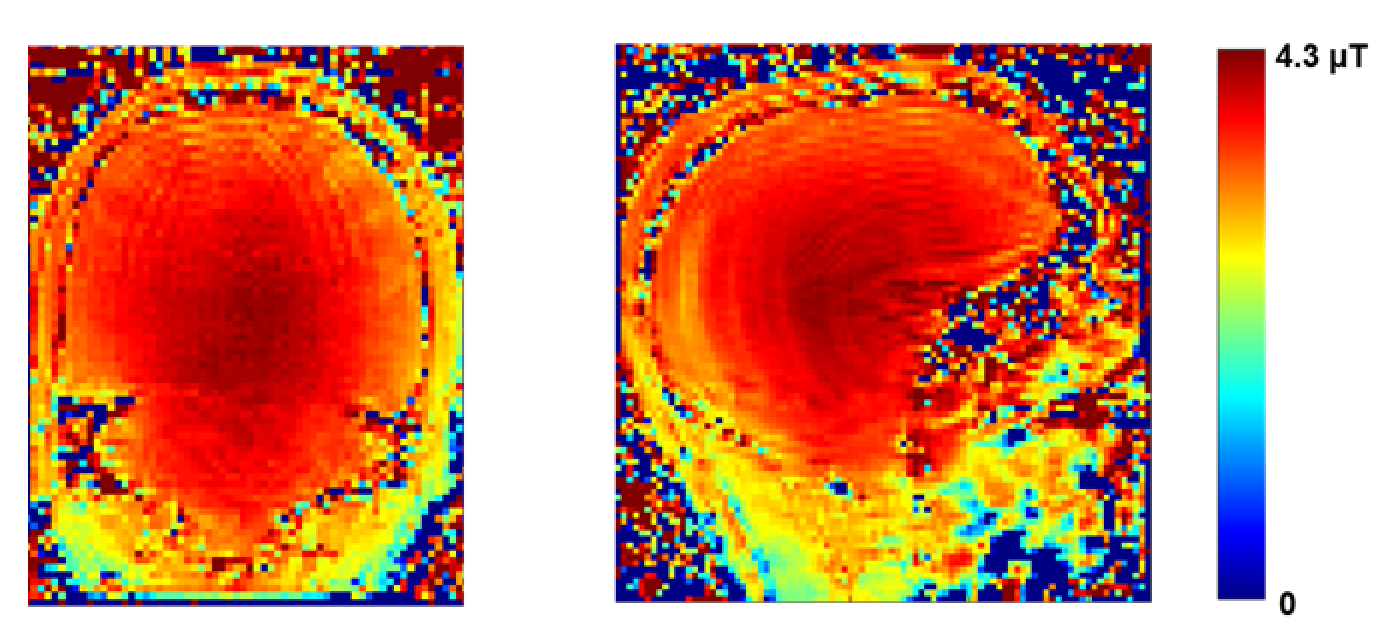
Our numerical observations included: (i) practically no influence of the birdcage coil axial shift on B1+ profiles (Fig. 3a and 4a); small variations were observed only in region of skull and scalp. (ii) A substantial influence of the birdcage coil axial shift on SAR10g (Fig. 3b and 4b). Variation of the maximum SAR10g over the investigated set of coil axial shifts was 42% and 31% for the 1st and 2nd human models, respectively. (iii) Reference voltages (Vr) for generation of 11.7µT over the axial slice as 311V and 318V for the 1st and 2nd human models, respectively. The experimental B1+ maps obtained for Vr of 327V is presented on Fig.5. It was impossible to make quantitative comparison of numerical and measurement results because none of human models were derived from the subject used for experimental B1+ mapping. A qualitative comparison was done based on Vr and shapes of experimental B1+ profiles (Fig. 5). From our database Vr for the Connectom scanner were in the range from 308 V to 352 V over 50 human subjects scanned in this scanner. Thus the Vr for numerical models were within the range. Even if the numerical model is derived from the subject used for B1+ mapping it is a challenge to get reliable validation (using B1+ mapping) of the numerical model for a given scanner in terms of generated SAR10g. Limitations of used B1+ mapping technique include: (i) the double angle method for B1 mapping assumes a linear relationship between the nominal flip angles entered and the actual B1+ amplitudes, (ii) signal to noise ratio at periphery (locations where B1+ varies due to coil axial shift) is rather low. In general B1+ mapping results cannot be obtained from skull. Maximum value of SAR10g more than 20 W/kg in a region below eye was observed for the 2nd human model. For this model there is no RF safety margin in the Connectom scanner in term of SAR10g exposure limit defined by IEC Standard 60601-2-33.Conclusion
Our simulations provide evidence that (i) RF exposure at level of 3.2W/kg head SAR can result in up to 21.4W/kg SAR10g in the Connectom scanner; (ii) B1+ mapping alone cannot be used for validation of the numerical model of whole-body birdcage coil of 3T Connectom scanner, (iii) developed RF circuit and 3D-EM co-simulation approach with reverse engineering based on phantom experimental results allowed obtaining reasonable quantitative agreement between coil transmit voltage and B1+ magnitude in human subjects.Acknowledgements
No acknowledgement found.References
1. Medical Electrical Equipment-Part 2–33: Particular Requirements for the Basic Safety and Essential Performance of Magnetic Resonance Equipment for Medical Diagnosis. International Electrotechnical Commission Standard 60601-2-33 Ed. 3, Geneva, Switzerland, 2010.
2. Kalloch, B., Bode, J., Kozlov, M., Pampel, A., Hlawitschka, M., Sehm, B., Villringer, A., Möller, H. E., Bazin, P.‐L. Semi‐automated generation of individual computational models of the human head and torso from MR images. Magnetic Resonance in Medicine, 81(3), 2090-2105 (2019).
3. Kozlov, M.; Horner, M.; Kainz, W.; Weiskopf, N.; Möller, H. E.: Modeling radio-frequency energy-induced heating due to the presence of transcranial electric stimulation setup at 3T. Magnetic Resonance Materials in Physics, Biology and Medicine 33, pp. 793 - 807 (2020).
4 Hasgall, PA, Di Gennaro, F., Baumgartner, C., Neufeld, E., Gosselin, MC., Payne, D., Klingenböck, A., Kuster, N., “IT’IS Database for thermal and electromagnetic parameters of biological tissues,” Version 3.0, September 1, 2015. www.itis.ethz.ch/database.
5. Stollberger, R., Wach, P. Imaging of the active B1 field in vivo. Magnetic Resonance in Medicine, 35 (2), pp. 245-251 (1996).
Figures