2485
Acoustic evaluation of carbon fiber RF shield structure for a 3T head-only imaging system1GE Global Research, Niskayuna, NY, United States
Synopsis
In this work we evaluate the MRI acoustic changes brought about by modifying the RF shield structure in a head-only (MAGNUS) 3T imaging system. Specifically, we use a standardized acoustic measurement protocol to compare sound pressure levels (SPL) in a fiberglass patient-bore structure to a similar newly developed carbon fiber reinforced polymer (CFRP) structure. Results indicate that a modification of the structural properties of the patient-bore structure properties can provide SPL reduction for MR imaging applications, and is likely due to the different modulus of elasticity between the two materials.
Purpose
Sound pressure waves created from the gradient coil moving in a main magnetic field create audible acoustic noise in MRI, which can pose a significant safety risk to the patient and operator. Previous work has focused on sound pressure level (SPL) reduction through various software [1-5] and hardware [6-8] approaches. Here we present data suggesting that the patient-bore structure, a standard component of most clinical MRI scanners, may be useful as an acoustic barrier for acoustic noise reduction. We provide an acoustic evaluation and comparison between a standard fiberglass reinforced polymer (FRP) patient-bore structure and a newly developed carbon fiber reinforced polymer (CFRP) weave patient-bore structure.Methods
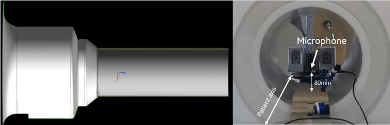
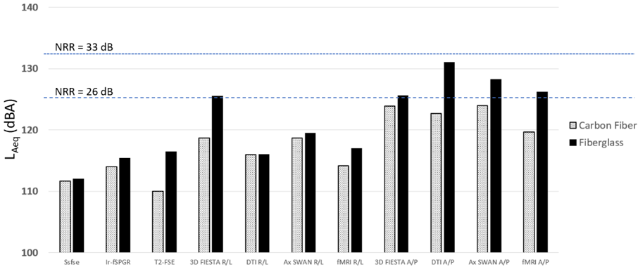
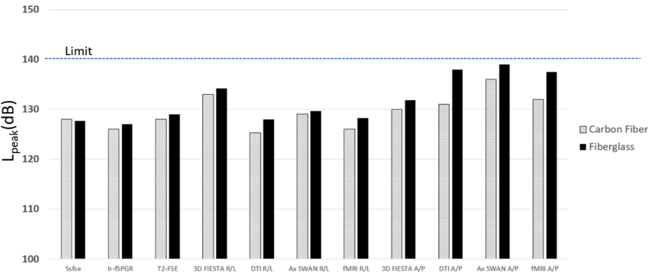
The patient-bore stepped cylindrical structure can be seen in Figure 1 (Left). It has a stepped profile that accommodates the 42-diameter gradient bore, and flairs to meet the 90-cm warm bore of the 3T magnet. As a requirement to eliminate interaction between the transmit/receive RF coil and the gradient coils, a stainless-steel mesh was mounted on the outside of the patient-bore structure to serve as the system RF shield when the structure was constructed from FRP. With the patient-bore structure constructed from CFRP, the stainless-steel mesh was not necessary and was not used. This was because CFRP has high electrical conductivity at high-frequency and can thus serve as an RF shield and also provide structural strength to the patient-bore structure. However, the focus of this work was in reduction of acoustic noise. Acoustic measurements were made using (i) the standard FRP patient-bore structure and (ii) the CFRP structure of the same dimensions as for the FRP version. The acoustic measurement configuration inside the scanner bore is visualized in Figure 1 (Right) and was repeated for both test cases. Multiple scan sequences representing clinically relevant imaging protocols were tested, following the maximum clinical acoustic noise (MCAN) protocol defined by [9]. The gradient waveforms were measured using an oscilloscope to ensure identical duty cycles, gradient amplitudes, and slew rates for the corresponding sequences in both test arrangements. Acoustic measurements were made using a Model G4, Type 2250 handheld analyzer and Type 4189 microphone (Brüel & Kjær, Nærum, Denmark). The microphone was placed at the imaging isocenter, perpendicular to the patient axis, 80mm above the patient table. The A-weighted, equivalent continuous sound level was recorded in decibels (LAeq, dBA), along with the unweighted peak sound level (Lpeak, dB). SPL test results for 11 clinical sequences or MRI pulse sequence variations are summarized in Figures 2 and 3.Results and Discussion
The CFRP patient-bore structure provided an average of 3.6 dBA, and a maximum 8 dBA reduction in LAeq relative to the FRP patient-bore structure. Similar results were seen for peak sound SPL measurements, Lpeak , with an average of 2.3 dB, and a maximum 7 dB reduction (Figures 2 and 3). The variation of the measured SPL between different pulse sequences is expected since different pulse sequences have different waveform frequency content. We note that every sequence was played identically for each test case, so there was no difference in waveform frequency content for the same pulse sequence in different test arrangements. The results indicate that the use of CFRP for the patient-bore structure is a viable option for MRI scanner hardware noise derating. The reduction in SPL was likely due to the different modulus of elasticity between the materials (240 GPa for CFRP versus 90 GPa for FRP). The findings indicate that material selection for the patient-bore structure and any other structures within the magnet warm bore is an important consideration in SPL management for high-performance MRI scanners, especially at higher field strengths and/or even higher performance gradient coils [10].Acknowledgements
Eric Fiveland and Charles Seeley at GE Global Research.References
[1] Idiyatullin D, Corum C, Park J-Y, Garwood M. Fast and quiet MRI using a swept radiofrequency. J Magn Reson. 2006; 181(2):342–349. [PubMed: 16782371]
[2] Hennel F. Fast spin echo and fast gradient echo MRI with low acoustic noise. J Magn Reson Imaging. 2001; 13(6):960–6. [PubMed: 11382960]
[3] Segbers M, Rizzo Sierra CV, Duifhuis H, Hoogduin JM. Shaping and timing gradient pulses to reduce MRI acoustic noise. Magn Reson Med. 2010; 64(2):546–53. [PubMed: 20665798]
[4] Heismann B, Ott M, Grodzki D. Sequence-based acoustic noise reduction of clinical MRI scans. Magn Reson Med. 2014; 73(3):1104–9. [PubMed: 24889327]
[5] Tan ET, Hardy CJ, Shu Y, In MH, Guidon A, Huston J 3rd, Bernstein MA, Foo TKF. Reduced acoustic noise in diffusion tensor imaging on a compact MRI system. Magn Reson Med 2018; 79: 2902-11. [PMID: 28971512]
[6] Mansfield P, Chapman BL, Bowtell R, Glover P, Coxon R, Harvey PR. Active acoustic screening: reduction of noise in gradient coils by Lorentz force balancing. Magn Reson Med. 1995; 33(2):276–281. [PubMed: 7707921]
[7] Bowtell RW, Mansfield P. Quiet transverse gradient coils: Lorentz force balanced designs using geometrical similitude. Magn Reson Med. 1995; 34(3):494–497. [PubMed: 7500892]
[8] Edelstein WA, Hedeen RA, Mallozzi RP, El-Hamamsy SA, Ackermann RA, Havens TJ. Making MRI quieter. Magn Reson Imaging. 2002 Feb; 20(2):155–63. [PubMed: 12034336]
[9] ACOUSTIC NOISE MEASUREMENT PROCEDURE FOR DIAGNOSTIC MAGNETIC RESONANCE IMAGING DEVICES. NEMA-MS 4. National Electrical Manufacturers Association. 2010
[10] Foo TKF, Tan ET, Vermilyea ME, et al. Highly efficient head-only magnetic field insert gradient coil for achieving simultaneous high gradient amplitude and slew rate at 3.0T (MAGNUS) for brain microstructure imaging. Magn Reson Med. 2020;83:2356–2369.
Figures