2482
Thermal simulations for a high power diffusion weighting MR gradient coil1Dept.of Radiology, Medical Physics, University Medical Center Freiburg, Freiburg, Germany
Synopsis
In the context of the development of a high power MR diffusion probe for the human breast, a computer model for thermal simulation was created that allows evaluation of different duty cycles and current strengths. The proposed method includes simulating constant effective currents rather than time resolved pulse sequences. This allows reasonable computational effort to analyze the heating effects for a given diffusion weighting sequence on a given gradient system. The simulated results show reasonable agreement with experimental data.
Introduction
Diffusion weighting in MR imaging allows valuable contrast between healthy and tumorous tissue1. However, this method requires high current strengths within the respective diffusion weighting coils. Since the unavoidable resistive heating of the gradient system limits the possible duty cycle and b value, as well as it might imply patient safety risk and limited patient comfort, thermal predictive control is a desirable entity. Therefore, in the context of the development of a high power MR diffusion probe for the human breast2, a computer model for thermal simulation was created that allows evaluation of different duty cycles and current strengths.Methods
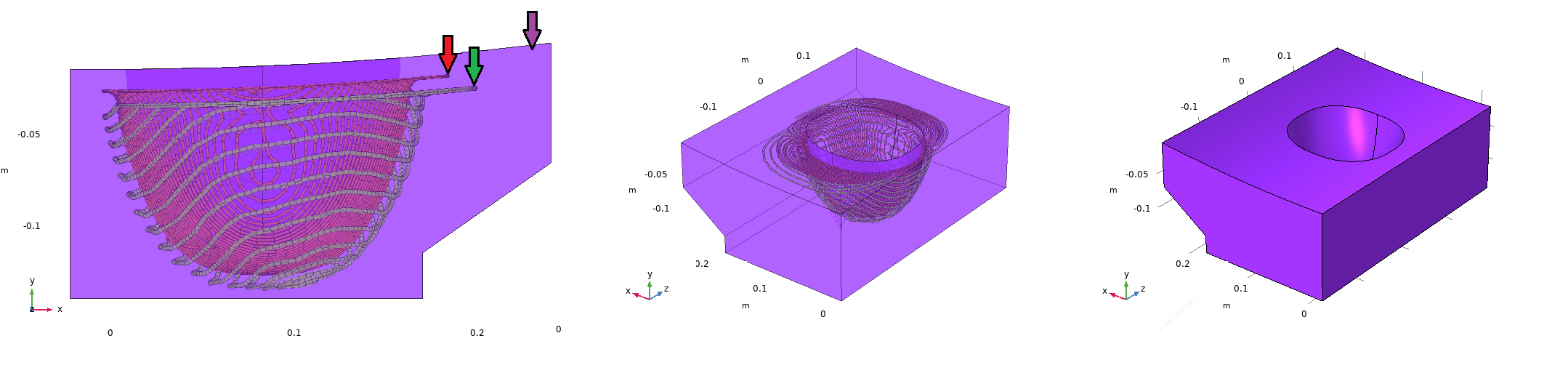
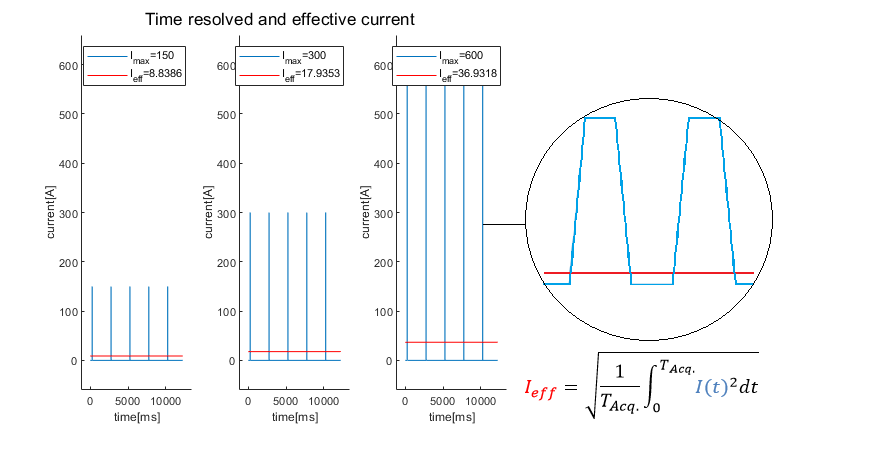
The setup of the simulation consists of the geometric representation of the actual coil as well as modelling the physics within the gradient coil while operational. Regarding the geometry, the real coil system was modeled by breaking it down into three components and materials [See Fig.1]: The copper current carrying wire track, silicon rubber cooling-tubes carrying the water coolant and finally the volumetric epoxy cast which embodies the first two components. In terms of the physical representation, computational times were realized by the following simplifications: Instead of the time resolved current of the diffusion weighting sequence, an effective current is being calculated that emits the same power within the coil. [See Fig.2]. This allows decreasing the time resolution from milliseconds to seconds. Concerning modelling , fluid dynamics were first included but later discarded since over boarding calculation effort. Instead the surface of the water carrying cooling tubes were set to a constant value of temperature of the in-flowing cooling water. A necessary condition is the flow velocity being high enough to be able to neglect the temperature change along the tube track. Therefore, the surface of the cooling tubes can be considered as a constant heat sink. Regarding the electric heating, the current density is assumed to be constant within and along the coils copper conductor. Respectively, the copper surface acts as constant heat source which heat flux can be calculated by the effective current, the coil resistance and its surface area. For experimental validation, virtual temperature probe points were set at similar positions of the thermal sensors within the actual coil. All simulation were performed with COMSOL MULTIPHYSICS3. Time resolution was chosen in steps of 30 seconds with a total simulation time of 10 minutes.Results
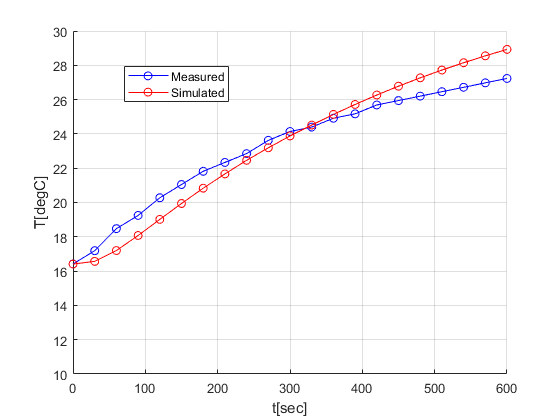
A single simulation needed 4 hours on a modern office PC. Temperature data can be extracted individually for the copper conductor, the surface of the model and the probe point of the thermal sensor. The surface temperature distribution pattern shows high agreement with experimental heat camera images. [See Fig.3] However, the measured average surface temperature is about 2° lower with a slight different curve trend. [See Fig.4].Disussion
In general, taken the multiple simplifications into account, the simulated data is in good agreement with measured. From the results regarding sequence duration, duty cycle and b value limits regarding patient and device safety can be defined for any desired sequence. Note that shown heating in figure No.4 for the modeled diffusion sequence with tR=200ms, duty cycle of 25% and b=118700s/mm² should be interpreted as a worst case scenario. In reality the MR signal will be decayed since de-phasing effects by the high diffusion gradients.Conclusion
The presented heat simulations allow predictive assessment of the thermal performance for the new high power diffusion weighting MR probe for the female breast. The proposed method off simulating effective currents rather than time resolved pulse sequences allows reasonable computational effort to analyze the heating effects for a given diffusion weighting sequence on a given gradient system.Acknowledgements
German Research Foundation (Grant Number ZA 422/5‐1)References
- O'Flynn, E.A.M., et al., Diffusion-Weighted Imaging of the High-Risk Breast: Apparent Diffusion Coefficient Values and Their Relationship to Breast Density. Journal of Magnetic Resonance Imaging, 2014. 39(4): p. 805-811
- Jia F, Littin S, et al. Design of breast gradient coil with the control of field nonlinearity, ISMRM 2018 Paris p1757.
- https://www.comsol.de/comsol-multiphysics,Heat-transfer-module
Figures
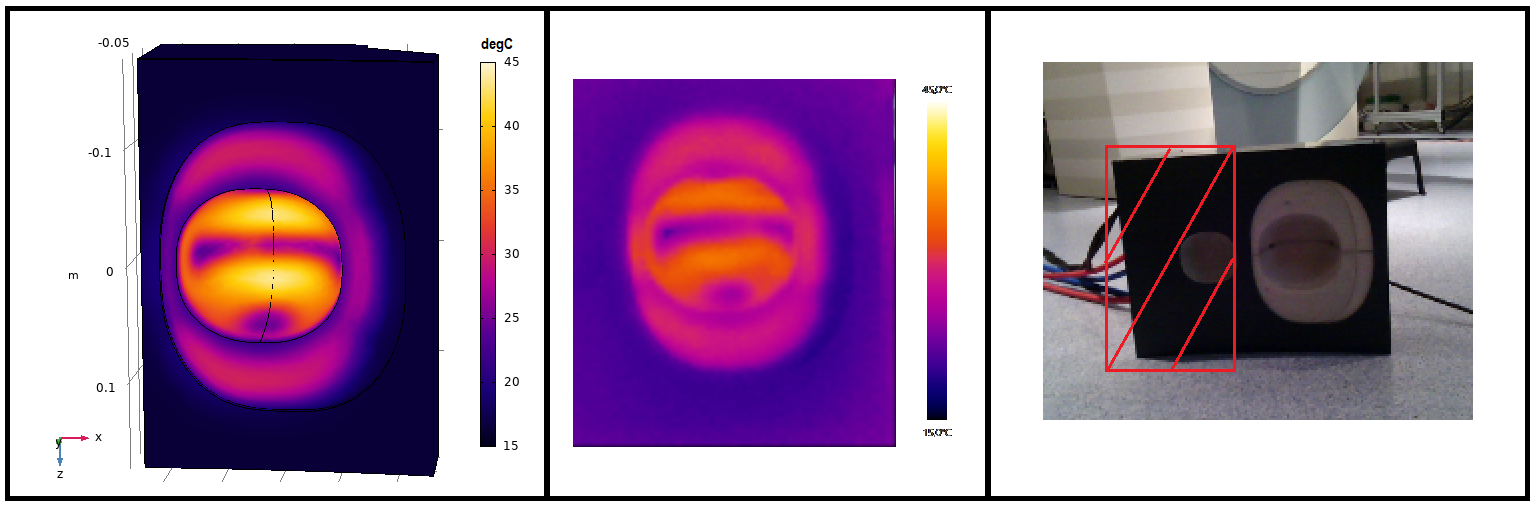
Comparison between simulated (left) and measured (middle) surface temperature after 6min permanent diffusion encoding with a b value of 101735 mm²/s. (Imax=100A,IEff≈50A, tR=200ms). Image of the actual coil (right). Note that left side of actual coil is not included in simulation since it does not contain any thermal active components.