2481
Design and Electric Field Analyses of a Shorter and Wider Asymmetric Gradient Coil for Whole Body MRI Scanners: A Comparison with a Symmetric Design1GE Global Research, Niskayuna, NY, United States
Synopsis
A unique approach to providing a more open, less claustrophobic whole-body MRI is presented. A design for an asymmetric gradient coil moves the region of interest (ROI) towards one end of the gradient coil, shortening the gradient coil length from the isocenter to the patient opening. This results in a stepped configuration where the patient-bore diameter outside of the imaging ROI is substantially wider compared to using a conventional symmetric gradient coil design. The stepped patient bore has previously been used in head-only gradient systems where the greater openness has resulted in increased patient comfort and reduced claustrophobia.
Introduction
Symmetric whole-body gradient coils (sWBG) are widely used in whole-body magnetic resonance imaging (MRI) scanners. The long cylindrical geometry of symmetric gradient coils limits the patient bore space, even at 70 cm. There is still a significant incidence of claustrophobia or reports of patient discomfort due to the constrained space1. One method for increasing the patient bore size is to increase the size of the magnet warm bore, and the corresponding gradient coil inner diameter. However, this comes at an increased magnet size and cost to maintain, and also reduced gradient coil efficiency from the larger diameter gradient coil2,3.Purpose
The goals of this work are: (1) Design a transverse asymmetric whole-body gradient coil (aWBG) and compare the performance to that of a symmetric design (sWBG). (2) The free-space electric field ($$$\vec{E}$$$-field) of the aWBG coil is compared to that of the sWBG coil as an assessment of peripheral nerve stimulation (PNS), as an indication of magneto-stimulation levels4.Materials and Methods
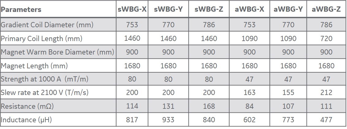
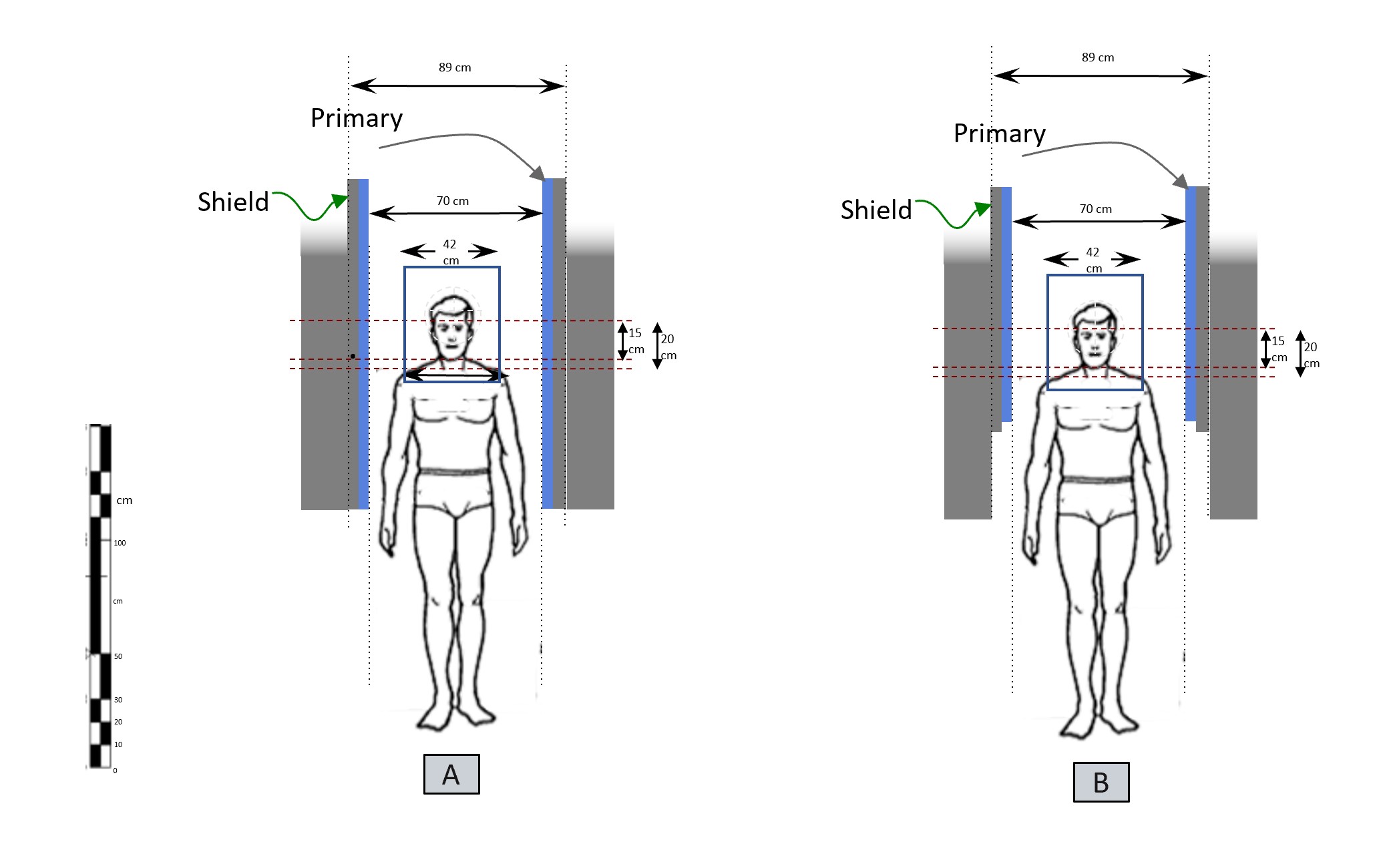
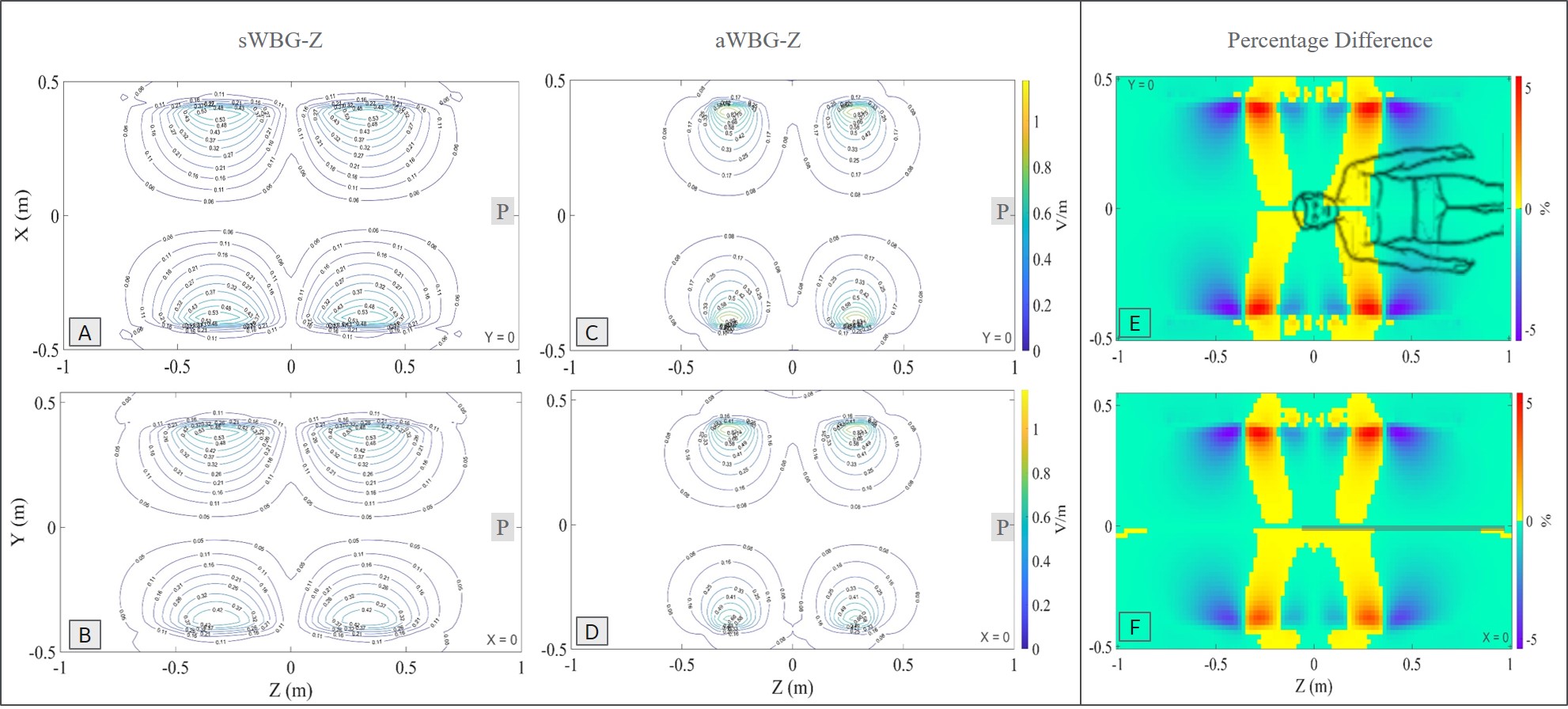
Design of aWBG: The aWBG design was carried out using custom tool written in MATLAB (Matworks,MA,USA). A finite element method with boundary current sources was used to optimize the current density created by a two-dimensional stream function. The actively shielded gradient coil was designed for a gradient driver current and voltage specification of 900 A and 2000 V respectively. An axially asymmetric design was adopted for the transverse coils and a symmetric design was used for the z coils. The bore diameter of the sWBG and aWBG coils outside the FOV at the patient end are 960 mm and 753 mm respectively. The bore diameter inside the FOV to the service end remains the same (753 mm) for the two coils (Figure 1). The length of the aWBG gradient coil from the isocenter to the patient end is shorter (400 mm) compared to the sWBG design that is 780 mm long. More details of the sWBG and aWBG coils are summarized in Table 1.Analyses: After normalizing the gradient amplitude (Gmax) of the coils to 10 mT/m, the magnetic vector potential field (A-field) and the corresponding magnetic field of the designed gradients were calculated directly using the Biot-Savart Law in a 3D grid of 2 x 2 x 2 mm3 spatial resolution. The obtained A-field was used to calculate the E-field in free space at 1 kHz (steady state sinusoid) for the y and z coils. Percent difference in the E-field magnitudes were calculated relative to a rheobase of 6.2 V/m6.
Results and Discussions
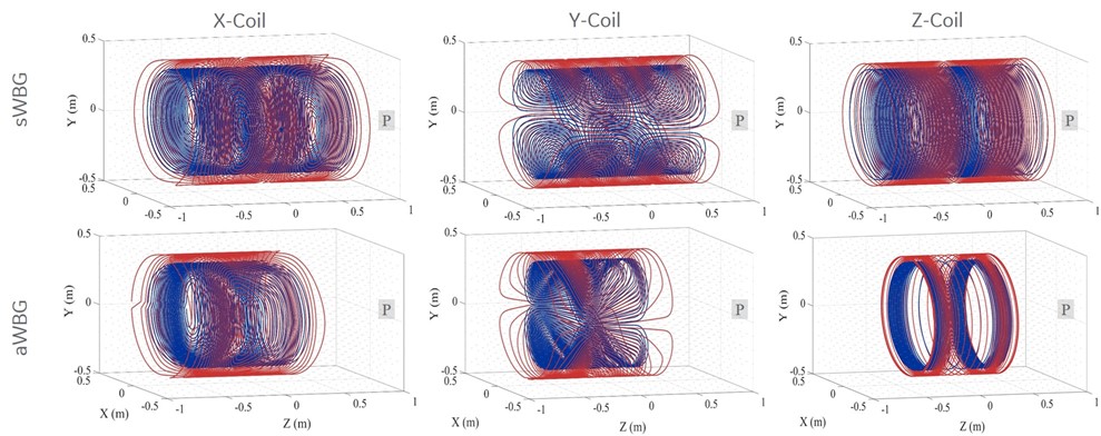
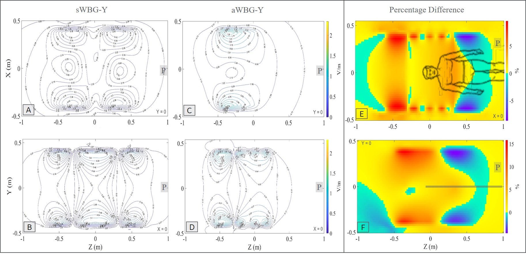
The inner diameter of the sWBG and aWBG coils were measured in the imaging region, and also outside of the imaging region at the patient end. These were 753 mm diameter within the imaging region, and 890 mm outside of the aWBG coil at the patient end (Figure 1). The gradient inner diameter in the imaging region to the service end remained the same at 753 mm for the two coils. The length of the aWBG gradient coil from the isocenter to the patient end was shorter (400 mm) compared to the sWBG design (780 mm). The 890 mm bore would be the largest for any MRI system. The aWBG coil length from the isocenter to.the patient end was about 50% shorter compared to the sWBG coil. Data for the sWBG and aWBG coils are summarized in Table 1The primary and shield coil turns of the aWBG and sWBG designs are shown in 3D for the x, y and z gradient axes in Figure 2. The $$$ |\vec{E}|$$$-field magnitude as well as difference between the the sWBG and aWBG designs for the y and z coils are shown in Figures 3-4. $$$\vec{E}$$$-field difference was high as 14% between the sWBG and aWBG y-gradient coils in the coronal plane, and 9% in the axial plane (Figure 3). With the lower inductance of the aWBG of 602 mH compared to 817 mH of the sWBG, the maximum gradient amplitude achieved with the aWBG design was 47 mT/m compared to 80 mT/m of the sWBG. This reduction in attainable $$$G_{max}$$$ on the aWBG coil can be attributed to the lesser coil efficiency of the asymmetric coil design. The aWBG transverse coil design delivered an $$$SR_{max}$$$ of 163 T/m/s and 155 T/m/s in the x and y directions, respectively. The z-coil gave an $$$SR_{max}$$$ of 212 T/m/s. The aWBG coil has a lower $$$SR_{max}$$$ compared to the sWBG coil despite its lower inductance because of its lower coil efficiency. Lower $$$\vec{E}$$$-field values were obtained for the aWBG coil compared to the sWBG around the head and abdomen of the human overlay (Figures 3-4). The aWBG y-coil resulted higher $$$\vec{E}$$$-field values (compared to the sWBG coil) on the service end and about comparable values in the chest region. This increase in $$$\vec{E}$$$-field values may be attributed to increased coil turn density of the aWBG coil, especially at the service end of the coil.Conclusion
We have analyzed the design and $$$\vec{E}$$$-fields of an asymmetric gradient coil for a whole-body MR system to provide a more open stepped patient bore. The lower aWBG coil efficiency (compared to sWBG) can be addressed by adopting a more powerful gradient driver.Acknowledgements
No acknowledgement found.References
[1] Y. Wang, F. Liu, Y. Li, F. Tang, and S. Crozier, “Asymmetric gradient coil design for use in a short, open bore magnetic resonance imaging scanner,” Journal of Magnetic Resonance, vol. 269, pp. 203–212, Aug. 2016, doi: 10.1016/j.jmr.2016.06.015.
[2] D. Tomasi, R. F. Xavier, B. Foerster, H. Panepucci, A. Tannús, and E. L. Vidoto, “Asymmetrical gradient coil for head imaging,” Magnetic Resonance in Medicine, vol. 48, no. 4, pp. 707–714, 2002, doi: 10.1002/mrm.10263.
[3] T. K. F. Foo et al., “Highly efficient head-only magnetic field insert gradient coil for achieving simultaneous high gradient amplitude and slew rate at 3.0T (MAGNUS) for brain microstructure imaging,” Magnetic Resonance in Medicine, vol. 83, no. 6, pp. 2356–2369, 2020, doi: 10.1002/mrm.28087.
[4] M. Bencsik, R. Bowtell, and R. M. Bowley, “Using the vector potential in evaluating the likelihood of peripheral nerve stimulation due to switched magnetic field gradients,” Magnetic Resonance in Medicine, vol. 50, no. 2, pp. 405–410, 2003, doi: 10.1002/mrm.10520.
[5] C. Niu et al., “Numerical Design of High-Efficiency Whole-Body Gradient Coils With a Hybrid Cylindrical-Planar Structure,” IEEE Transactions on Biomedical Engineering, vol. 66, no. 6, pp. 1628–1636, Jun. 2019, doi: 10.1109/TBME.2018.2877429.
[6] W. Irnich and F. X. Hebrank, “Stimulation threshold comparison of time-varying magnetic pulses with different waveforms,” Journal of Magnetic Resonance Imaging, vol. 29, no. 1, pp. 229–236, 2009, doi: 10.1002/jmri.21573.
Figures