2479
Electric Field Calculation and PNS Prediction for Head and Body Gradient Coils1Department of Radiology, Stanford University, Stanford, CA, United States, 2Laboratory of Nanotechnology for Precision Medicine, Italian Institute of Technology, Genoa, Italy, 3Department of Medical Biophysics, Western University, London, ON, Canada, 4Robarts Research Institute, Western University, London, ON, Canada, 5Roemer Consulting, Lutz, FL, United States
Synopsis
Computationally efficient methods are presented which allow calculation of switched-gradient-induced electric field distributions on realistically sized body model with uniform interior properties (compatible with regulatory IEC standards). Electric fields were calculated for three classes of gradient coils (asymmetric head, symmetric head and body gradients) using 100-member male and female body model populations; these were then used to estimate population-mean PNS parameters which were validated against experimental PNS measurements, showing high accuracy. Our computationally efficient methods can calculate whole-body E-field distributions in seconds with updates for different gradient designs in tens of milliseconds, providing an important tool for PNS-constrained gradient design.
Introduction
Modern day high performance gradient systems are strongly limited by peripheral nerve stimulation. Head gradient coils, either asymmetric or symmetric, can provide higher PNS thresholds compared to body gradient coils. Although PNS limits for various gradient coils have been experimentally measured1-4, no comprehensive analyses have been performed especially for head gradient coils and especially including direct validation of calculated PNS thresholds against experimental measurements. Electric field calculations can be used to predict PNS thresholds according to the IEC 60601-2-33 safety standard5 and there is a substantial literature focused on switched-magnetic-coil-induced E-field calculations6,7. Here, we present computationally efficient methods for calculating gradient-induced E-fields on realistically sized uniform body models. Calculated E-fields were used to predict PNS parameters and validated against PNS measurements acquired from three very different gradient coils (two head and one body gradient coil).Theory and Methods
We defined simplified body models with uniform interior electrical properties (as required by the IEC standard5) but realistic head-neck-shoulder geometry, depicted in Figure 1. We hypothesized that despite the simplified body model, our calculated surface E-fields would accurately predict population-mean PNS thresholds. The 2.5th, 50th and 97.5th percentile dimensions for both male and female populations were obtained from the Humanscale reference manual8. Male and female populations of 100 body models each were generated assuming Gaussian distributions of dimensions; these populations were used to calculate population-mean E-fields and PNS thresholds. Total E-field in the low frequency magnetoquasistatic regime can be calculated as follows5:$$\vec{E} = -d\vec{A}/dt - \nabla\phi\qquad[1]$$where $$$\vec{A}$$$ is the vector potential produced by the gradient coil and $$$\phi$$$ is the electrostatic potential due to accumulated charges. A set of basis functions in the form of $$$U_m(u)V_n(v)$$$, with $$$u$$$ being angular coordinate and $$$v$$$ being axial coordinate, represented the surface charge density. $$$U_m(u)$$$ is either sine or cosine depending on gradient axis and $$$V_n(v)$$$ is a piecewise linear hat (triangle) function. Recognizing that the normal component of $$$\vec{E}$$$ must be zero on the surface of a uniform-interior body model, we can solve for the unknown weights of the charge basis functions. A weighted summation of E-fields generated by each basis function together with $$$d\vec{A}/dt$$$ provides the total E-field distribution. Peak surface E-fields are converted to population-mean PNS parameters ΔGmin and SRmin4,5. The above calculations were validated against experimental PNS measurements across a range of gradient coils for which we had sufficient information to calculate E-fields and for which PNS experimental data had been published: one symmetric folded head gradient coil (our own H3 design)2,10, one asymmetric head gradient coil (essentially equivalent to the GE HG2 head gradient coil9), and one conventional body gradient coil (the GE BRM body gradient coil1).Results
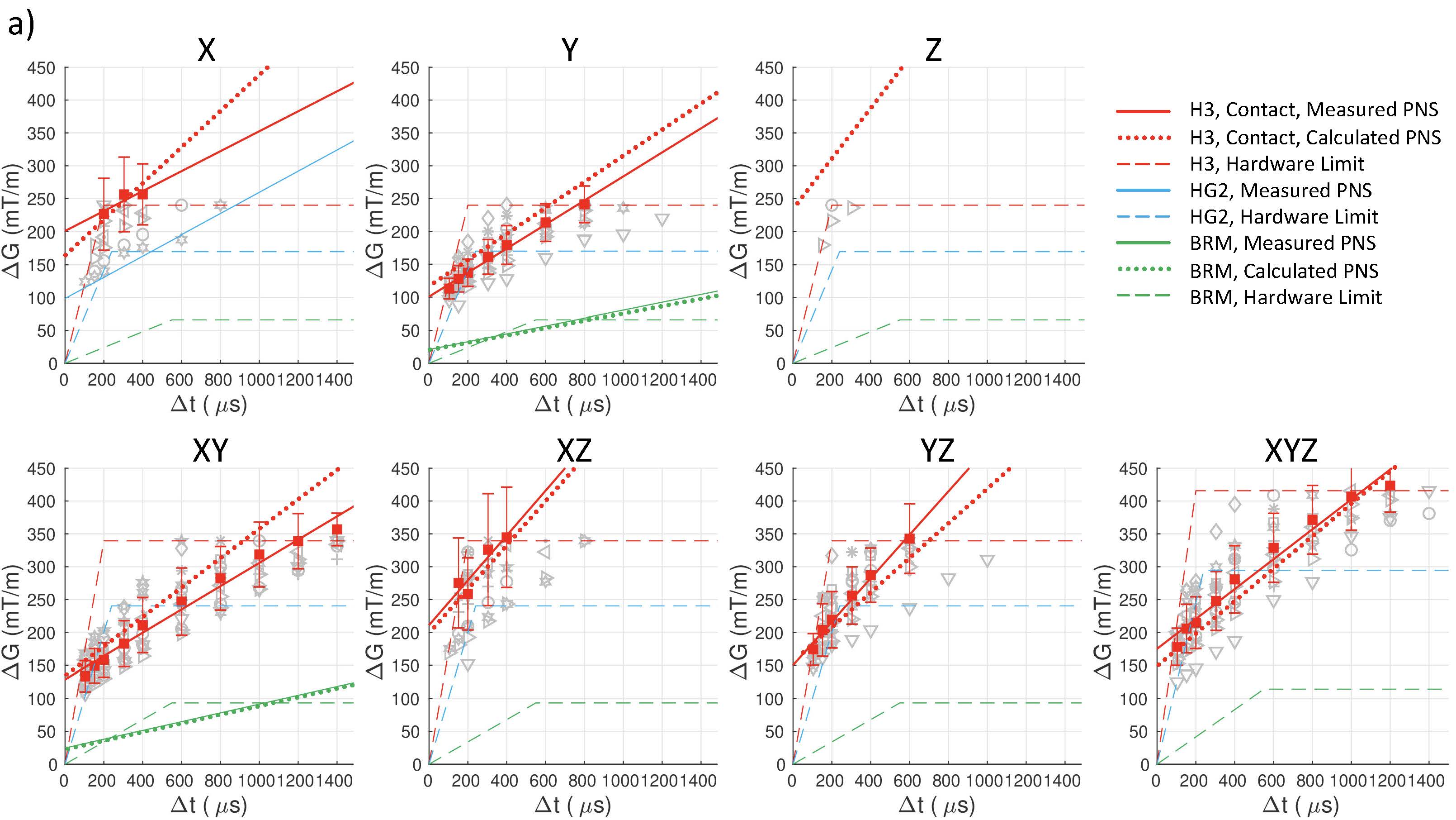
Calculated E-fields on the simplified body models are shown in Figure 2, which shows values and locations of peak surface E-fields. Locations are in approximate agreement with experimental reports1-3. Table 1 shows the comparison of calculated and measured PNS parameters for the H3 head gradient (at two body positions: shoulder-coil contact and 2cm shoulder-coil gap), while Table 2 shows the same for the two GE gradients (HG2 head gradient and BRM body gradient). For the head gradient coils, we calculated ∆Gmin using two different chronaxie values: the IEC-specified value (360 µs) as well as a longer value of 600 µs. This longer chronaxie value results in a significantly closer match to experimental data, especially for the H3 coil. Chronaxie values in the range of 600µs have consistently been observed in the literature1-3. Calculated results also show that the asymmetric head gradient (HG2) has lower X (vs Y) threshold while the symmetric head gradient (H3) demonstrates the opposite ordering; this is consistent with experimental findings. The overall prediction errors between our calculated PNS parameters and the corresponding experimentally measured values were 28% mean absolute error (using 360 µs chronaxie for all coils) or 18% MAE (using 600 µs chronaxie for head coils). Excluding low reliability measurements (coefficient of variation >10%), these overall errors reduced to 23% MAE (using 360 µs chronaxie for all coils) or 10% MAE (using 600 µs chronaxie for head coils). A comparison of individual and mean PNS measured thresholds, calculated PNS thresholds and hardware limits is presented in Figure 3.Discussion and Conclusion
Our computational methods predict population-mean PNS thresholds for three widely different gradient coils with high accuracy. PNS experiments are time consuming, expensive, and prone to error; this makes a computational approach attractive. We found that achieving maximum prediction accuracy for head gradient coils required the use of a longer chronaxie (~600 µs). Our methods generate whole-body E-field distributions in seconds with updates for different gradient designs in tens of milliseconds; this high speed will allow for practical PNS-optimized gradient design. We are currently using Sim4Life (ZMT MedTech AG, Zurich) to study E-fields differences between uniform body models and fully realistic, heterogenous-interior Virtual Family models11. The combination of computational speed, direct validation with high accuracy compared to matched experimental measurements, and regulatory compatibility, represents an advance over prior work. Our work demonstrates an important capability for predicting population-mean PNS thresholds with enough accuracy to be useful for a number of important applications in gradient design, development and analysis.Acknowledgements
We gratefully acknowledge the scientific contributions of Dr. Graeme McKinnon. We acknowledge research support from the National Institutes of Health (NIH P41 EB015891, NIH R01 EB025131 and NIH U01 EB025144). We acknowledge ZMT Zurich MedTech AG for their Sim4Science support. KE acknowledges the support of a research fellowship from the MINDED program, a Marie Skłodowska-Curie COFUND Action.References
[1] Zhang, B., Yen, Y.F., Chronik, B.A., McKinnon, G.C., Schaefer, D.J., and Rutt, B.K., Peripheral nerve stimulation properties of head and body gradient coils of various sizes. Magn Reson Med, 2003 50(1):50-8. doi: 10.1002/mrm.10508 [2] Wade, T., Alejski, A., McKenzie, C., and Rutt, B.K., Peripheral Nerve Stimulation Thresholds of a High Performance Insertable Head Gradient Coil. Proc ISMRM, 2016 [3] Lee, S.K., Mathieu, J.B., Graziani, D., Piel, J., Budesheim, E., Fiveland, E., Hardy, C.J., Tan, E.T., Amm, B., Foo, T.K., et al., Peripheral nerve stimulation characteristics of an asymmetric head-only gradient coil compatible with a high-channel-count receiver array. Magn Reson Med, 2016 76(6):1939-50. doi: 10.1002/mrm.26044. [4] Chronik, B.A. and Rutt, B.K., Simple linear formulation for magnetostimulation specific to MRI gradient coils. Magn Reson Med, 2001 45(5):916-9. doi: 10.1002/mrm.1121. [5] IEC, Medical electrical equipment – Part 2-33: Particular requirements for the basic safety and essential performance of magnetic resonance equipment for medical diagnosis. International Electrotechnical Commissioin 2015 60601-2-33 Edition 3.2 [6] Bencsik, M., Bowtell, R., and Bowley, R., Electric fields induced in the human body by time-varying magnetic field gradients in MRI: numerical calculations and correlation analysis. Phys Med Biol, 2007 52(9):2337-53. doi: 10.1088/0031-9155/52/9/001. [7] Liu, F., Zhao, H., and Crozier, S., On the induced electric field gradients in the human body for magnetic stimulation by gradient coils in MRI. IEEE Trans Biomed Eng, 2003 50(7):804-15. doi: 10.1109/TBME.2003.813538 [8] Diffrient, N., Tilley, A.R., and Bardagjy, J.C., Humanscale 1/2/3 Manual. Humanscale. 2017, Chicago, IL: IA Collaborative Ventures, LLC. [9] Tan, E.T., Lee, S.K., Weavers, P.T., Graziani, D., Piel, J.E., Shu, Y., Huston, J., 3rd, Bernstein, M.A., and Foo, T.K., High slew-rate head-only gradient for improving distortion in echo planar imaging: Preliminary experience. J Magn Reson Imaging, 2016 44(3):653-64. doi: 10.1002/jmri.25210. [10] Winkler, S.A., Schmitt, F., Landes, H., de Bever, J., Wade, T., Alejski, A., and Rutt, B.K., Gradient and shim technologies for ultra high field MRI. Neuroimage, 2018 168:59-70. doi: 10.1016/j.neuroimage.2016.11.033. [11] Gosselin, Marie-Christine, et al. "Development of a new generation of high-resolution anatomical models for medical device evaluation: the Virtual Population 3.0." Physics in Medicine & Biology 59.18 (2014): 5287.
Figures