2314
Influence of E-Field Homogeneity and Drift for Testing Medical Implants for RF-induced heating at 64MHz according to ASTM-F2182 and ISO/TS 109741MRI-STaR - Magnetic Resonance Institute for Safety, Technology and Research GmbH, Gelsenkirchen, Germany, 2TU Dortmund University, Dortmund, Germany, 3MR:comp GmbH, Testing Services for MR Safety & Compatibility, Gelsenkirchen, Germany
Synopsis
Medical implants of all kind must be tested for RF-induced heating to determine their MR safety and compatibility. Test conditions concerning E-field homogeneity and E-field drift during assessment time are defined in ISO/TS 10974 and ASTM-F2182. This study evaluates the influence of E-field drift and E-field homogeneity on RF-heating. It shows that both effects can lead to a temperature underestimation. Even for small implants whose volume is in a homogenous area within ±1dB, this underestimation can occur. System instability and implant size and position can further increase the underestimation of RF-induced heating and should be carefully considered.
Introduction
RF-induced heating is an MRI safety issue for patients with implanted devices. These implants must be tested according to ISO/TS 109741 or ASTM-F21822. Conditions and limits are defined for testing e.g., the incident E-field spatial variation must be within ±1dB/±12% and the drift less than 0.25dB during assessment.This study evaluates the influence of E-field homogeneity and drift on the RF-induced heating of several objects.
Methods
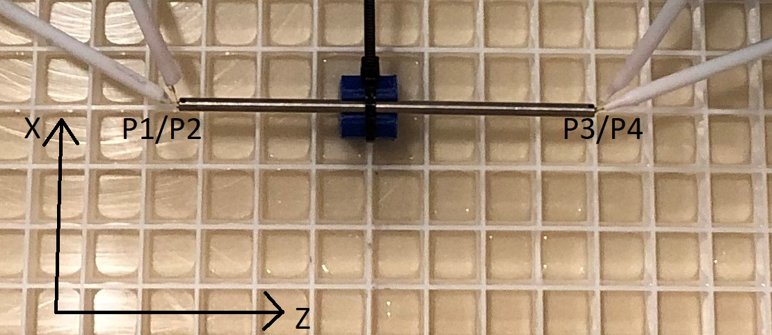
To investigate the influence of incident E-field homogeneity, two exposure systems were used. A Birdcage Coil (BC) with a field distribution according to Annex M1 (MITS System, Speag) and a Linear Exposure System (LES) (MR:comp GmbH), generating an E-field distribution along z-axis.The ASTM phantom (420mm x 90mm x 650mm), filled with saline solution (σ=0.47 S/m, εr=80), was used and E-field distributions were measured with an Erms probe (SAR Probe, EX3DV4, SPEAG) in both systems. The measured area is a 100x610mm xz-plane with 20mm distance to each wall (cf. Fig. 2).
In a second measurement, the test objects were placed successively in the phantom: a 100mm-long titanium rod (SAIMD-21,2), and three stainless steel rods (⌀= 6mm, length: 100mm, 200mm, 300mm).
For each measurement one rod was placed centrally with 6cm wall distance to reduce reflection effects3. Two fiber optic temperature probes were placed at each rod tip (cf .Fig. 1).
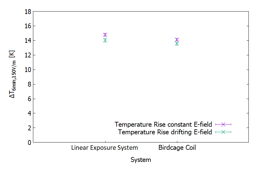
To investigate the influence of the E-field drift over measurement time, one test run where an E-field drift was tolerated and one test run where the E-field was kept constant by readjusting the applied power was done in each system with the titanium rod.
To investigate the influence of field homogeneity, the E-field was kept constant over the 6min exposure time for all further runs.
Temperature rise was measured for each object with and without object and was then scaled to an average incident E-field of 150V/m to compare results.
Results
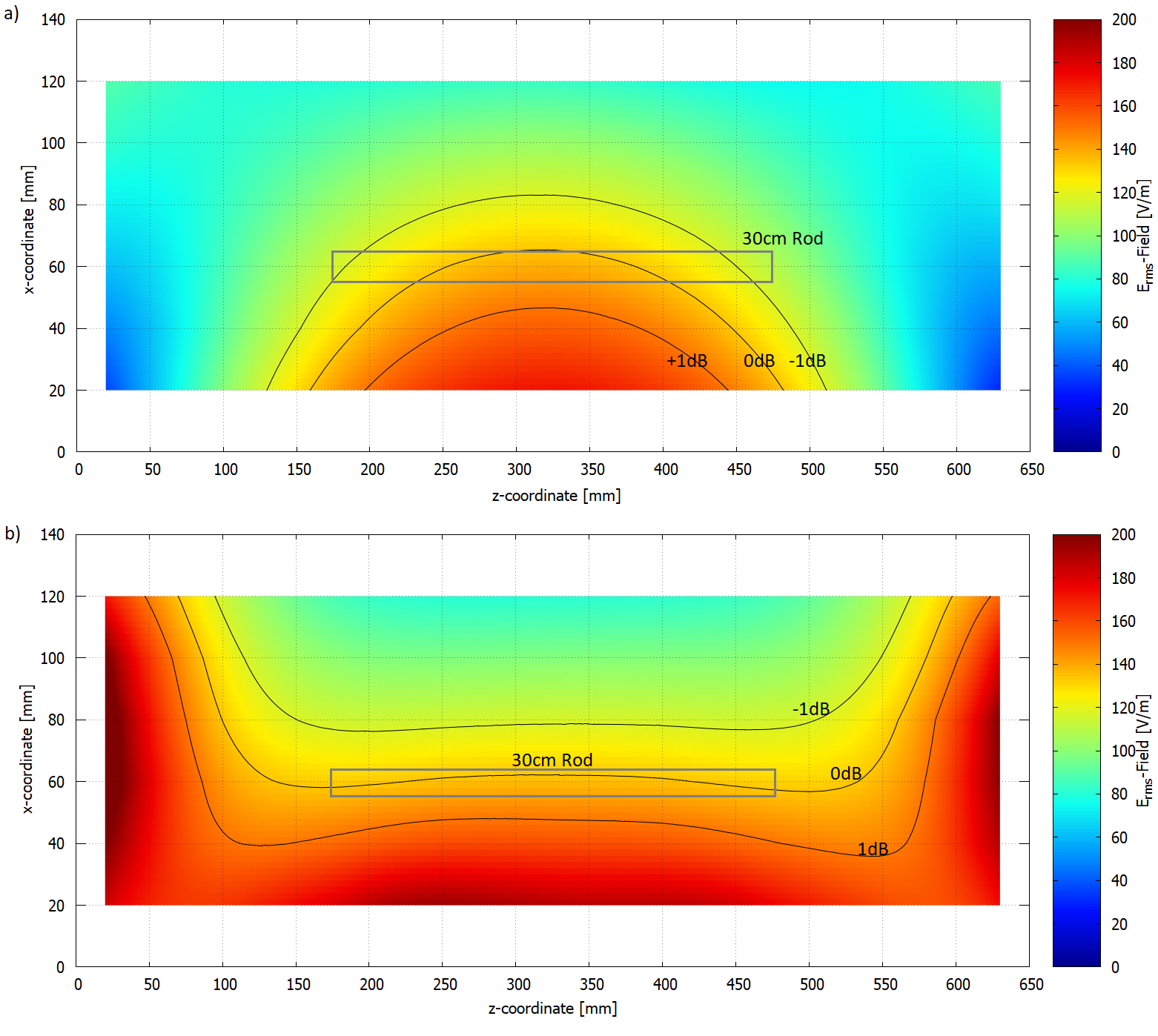
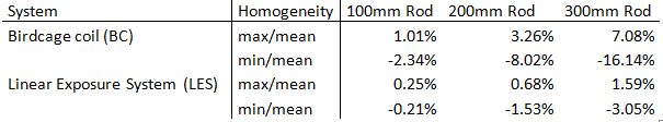
Measured Erms-Field distributions for BC and LES are shown in Fig. 2a/b. The 0dB and ±1dB isolines are shown in black and the grey rectangle represents the 300mm rod position as largest object.The results show, that the E-field of the LES is homogenous over the entire pathway of all objects. For the BC the E-field varies over the pathway (cf. Tab. 1).
The maximum E-field variations of the LES are between +1.59% and -3.05%. For the BC, homogeneity varies over the rod length. For 100mm and 200mm the homogeneity is less than ±12%, for the 300mm rod the field varies up to -16.14%.
The 100mm titanium rod is a well-defined object1,2. According to Annex I2, the target value for its temperature rise divided by square of incident E-field should be 0.66 mK/(V/m)2. The value for the titanium rod in the LES is 0.656±0.009 mK/(V/m)2. The values are in agreement and therefore the temperature rises from the LES are the target values for the BC measurement.
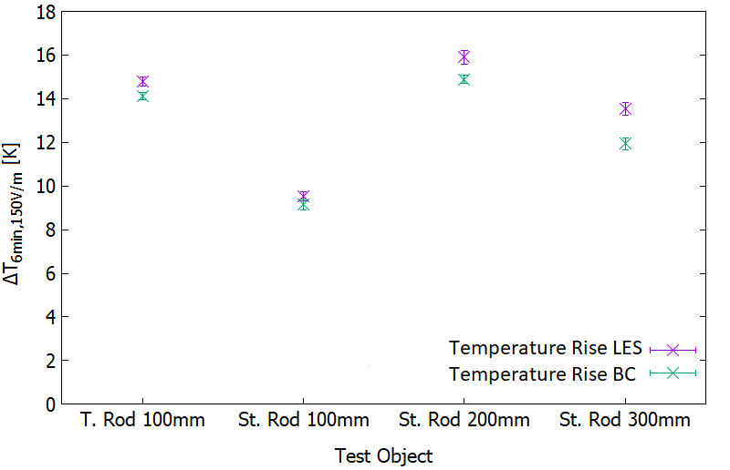
Results of temperature rise scaled to an average incident E-field of 150V/m for all four objects are shown in Fig. 3 for both systems.
Results in Fig 3 indicate, that the temperature rise measured in the BC is lower for all objects compared to LES. The difference between the values is increasing with E-field inhomogeneity. Temperature rises for both 100mm rods are 4.02% to 4.36%, for the 200m rod 6.40% and for the 300mm rod even 11.88% lower than the target values.
Results for the influence of the E-field drift are shown in Fig. 4. In both cases the E-field drops down by 7.5% to 8.0%, which leads to a lower temperature rise of 3.80% to 4.95%. The difference for constant E-field in the LES and drifting E-field in the BC amounts to 7.99%.
Discussion
The results in Tab. 1 indicate that the incident E-fields for the two 100mm rods and the 200mm rod varies less than 12% for both systems. However, even for the 200mm rod the temperature rise is underestimated by 6.40%. For the 300mm rod in the BC the inhomogeneity is up to 16.14% and the underestimation of the temperature rise is 11.88%, even though the volume outside the 12% criteria is relatively small (cf. Fig. 2a).The E-field drift leads to an additional underestimation of the temperature rise. Depending on the system’s temporal stability, object size and position, this underestimation could be considerably worse and should be taken into account.
Conclusion
This study shows that the E-field drift and homogeneity should be carefully considered when testing implants for RF-induced heating. Even for small implants, where the incident E-field varies less than 12%, the underestimation of temperature rise should not be neglected.Both effects should be further investigated for larger implants, like orthopedic implants, where the E-field inhomogeneity is even worse, which can lead to a major underestimation.
Acknowledgements
No acknowledgement found.References
1. Technical specification ISO/TS 10974:2018, “Assessment of the safety of magnetic resonance imaging for patients with an active implantable medical device,” The International Organization for Standardization, 2018.
2. ASTM F2182-19e2, “Standard Test Method for Measurement of Radio Frequency Induced Heating On or Near Passive Implants During Magnetic Resonance Imaging”, ASTM international, 2019.
3. M. Kozlov, M. Angelone, “Effect of Multiple Scattering on Heating Induced by Radio Frequency Energy”, IEEE T ELECTROMAGN C, Vol 62, No.5, October 2020.
Figures