2311
Input Impedance Comparison of MR-Conditional Cardiac Implantable Pulse Generators at the 1.5T MR Frequency of 63.87 MHz
Jason Meyers1, David Prutchi1, and Ramez Shehada2
1Impulse Dynamics (USA) Inc., Marlton, NJ, United States, 2Medical Technology Laboratories, La Mirada, CA, United States
1Impulse Dynamics (USA) Inc., Marlton, NJ, United States, 2Medical Technology Laboratories, La Mirada, CA, United States
Synopsis
The MR environment poses a tissue heating hazard to patients with cardiac IPGs (implantable pulse generators), such as pacemakers and defibrillators, due to RF currents circulating in the loop formed by the IPG, a transvenous lead, and the tissue. Heating will be limited by the impedance of this loop at the MR frequency (63.87 MHz for 1.5T). The IPG input impedance (a portion of this loop) was measured in six MR-Conditional IPG’s. All have a comparable, low impedance, suggesting that device manufacturers are not intentionally adding impedance and that some interchangeability may be possible without changing RF-induced heating.
Introduction and Background
The MR environment presents a number of potential hazards to patients with cardiac implantable electronic device systems. Tissue damage due to RF heating is one such hazard for which tests must be performed on a complete system consisting of an IPG (implantable pulse generator) and one or more leads. Practicalities limit the number of permutations that are tested.This leads to a lack of interchangeability between IPGs and leads which has numerous downsides for patients, including potentially requiring replacement of functional leads to maintain MR-conditional labeling and limiting therapy options. We measured the IPG characteristics relevant to the RF heating hazard. This, in combination with similar testing of MR-Conditional leads, should contribute to an understanding of cases in which interchanging IPGs and leads may be safe.
The MR environment has a strong RF field present at the Hydrogen precession frequency of 63.87MHz in a 1.5T MRI scanner. A system consisting of an IPG and a lead creates an electrical loop along the lead, through the IPG (from the lead connection to the IPG’s enclosure, referred to as the “Can”) and back to the end of the lead through tissue, as shown in Figure 1. The RF field induces current in this loop, which in turn causes heating (which is most concentrated at the distal "Tip" electrode). The magnitude of the circulating current, and therefore the heating, is dependent on the impedance of this loop.
In standard IPG construction, the Tip and Ring terminals of a lead attach to a connector block in the header. From there, a wire routes through a hermetic feedthrough and then connects to IPG circuitry inside the can. An EMI filtering capacitor just inside the Can will provide a low-loss path between the lead connection and the Can. As a first order model, the header block to Can impedance can be modeled as the series combination of the feedthrough wire impedance and the capacitor impedance.
Evaluating this model shows that the inductance of the feedthrough wire dominates, and that impedance magnitudes of around 1-5 Ω are to be expected, dependent primarily on wire length. We hypothesize that the impedance contributed by the IPG is a consequence of the standard methods of header construction employed by nearly all cardiac IPGs, that MR-conditional IPGs are not intentionally adding impedance at this frequency, and that therefore these IPGs will all present comparable impedances.
Methods and Results
Impedance measurements of six IPGs with MR-Conditional labeling were performed using a VNA (vector network analyzer). These test IPGs were modified to allow direct access to the Tip and Ring connectors by removing septum seals and, when necessary, machining a hole into the header. In each IPG, the header cavity closest to the Can was tested as it has the shortest feedthrough wires, resulting in the worst-case (lowest) impedance.A primarily 3D-printed test fixture was constructed to perform these measurements, as shown in Figure 2. The frame holds a probe arm which contains a contact point for the Can (adjacent to the header) and a contact point which reaches into the header. These contact points are assembled onto a small piece of hand-formable coaxial cable, which is terminated with an SMA connector to attach to the VNA. This construction method was adopted to minimize test fixture residuals.
The VNA was calibrated at the end of the test cable using a mechanical open-short-load calibration kit. The fixture was then installed, and the measurement reference plane was extended to the IPG connection. The complex reflection coefficient (S11) was measured and imported into Matlab, which was used to calculate the complex impedance and to apply an open-short impedance correction.
Measurement results are presented in Table 1 and plotted in Figure 3.
Discussion and Conclusions
All measured IPGs show an inductive impedance with a magnitude between 1 and 5.87 Ω. These values vary over this range primarily due to the feedthrough wire length and are congruent with the model described above. This shows that no additional impedance has been intentionally incorporated by the manufacturers of these devices to limit RF-induced electrode heating, showing that it is possible to achieve MR-conditional labeling with standard header construction, and suggesting that in some cases interchangeability may be possible without changing RF-induced heating.Acknowledgements
This work was supported by Impulse Dynamics (USA) Inc.References
No reference found.Figures
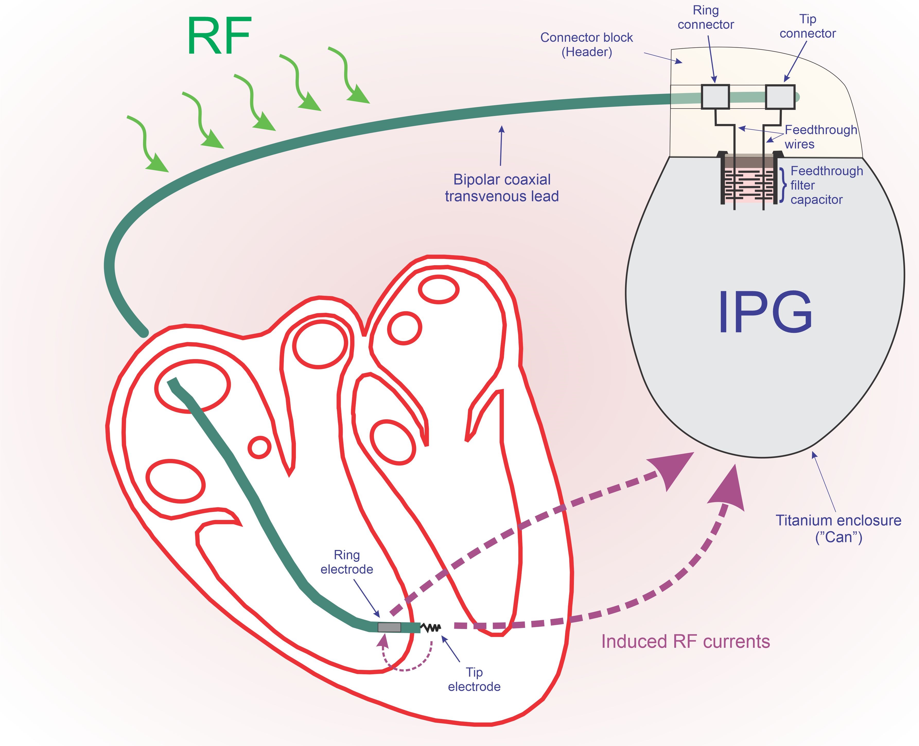
Figure 1: Simplified diagram showing the RF current circulation paths
that cause tissue heating.
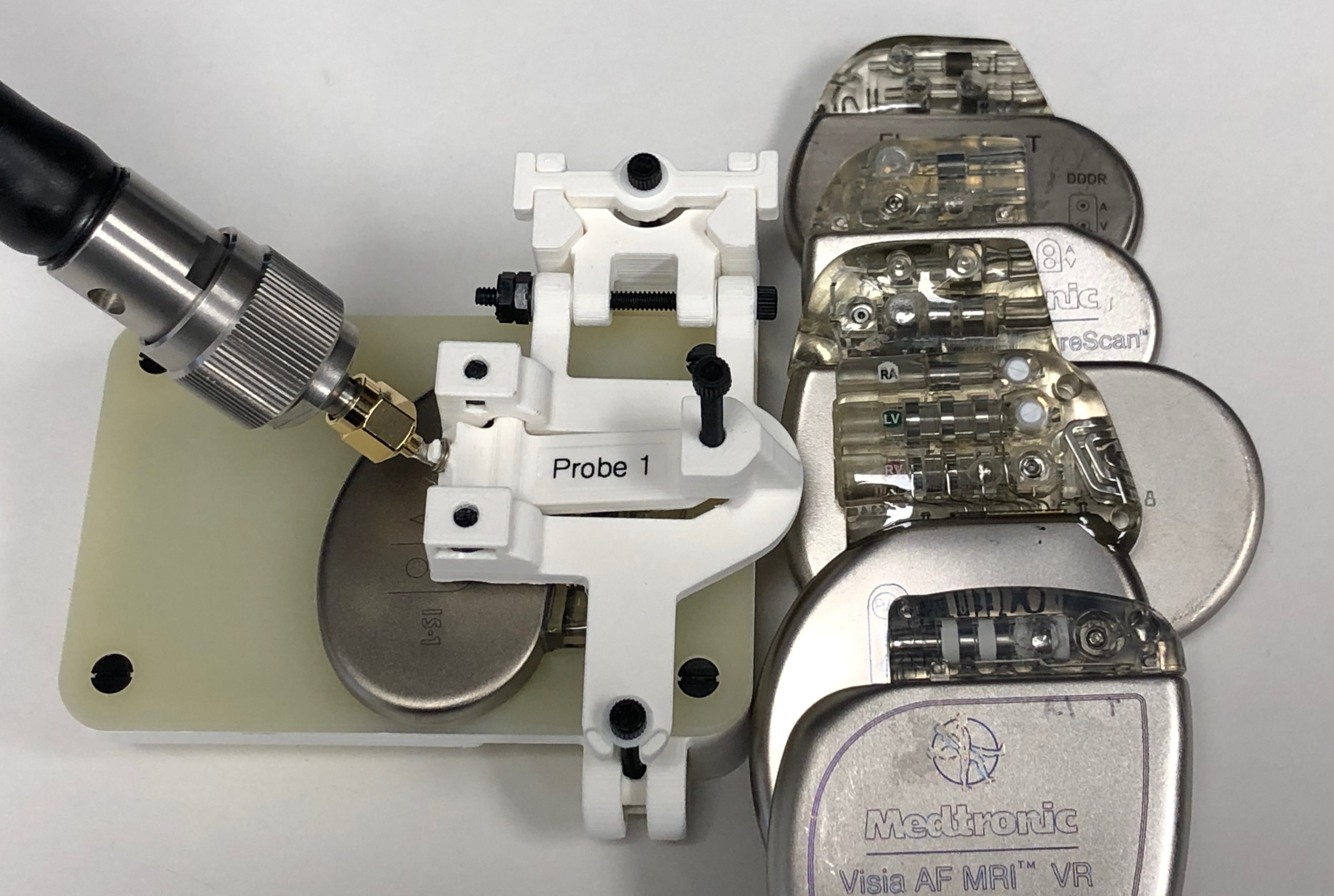
Figure 2: This test fixture was constructed to allow direct measurement
of the impedance between an IPG’s header connector block and Can. Also shown
are the IPGs modified to provide direct access to terminal blocks to allow this
measurement.
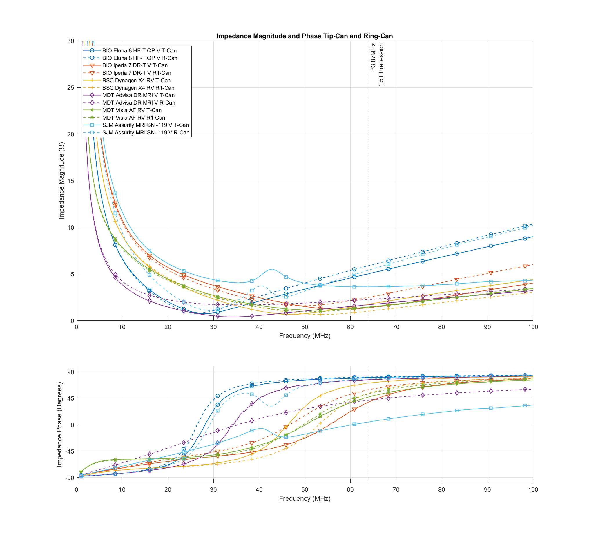
Figure 3: IPG input impedance measurement results
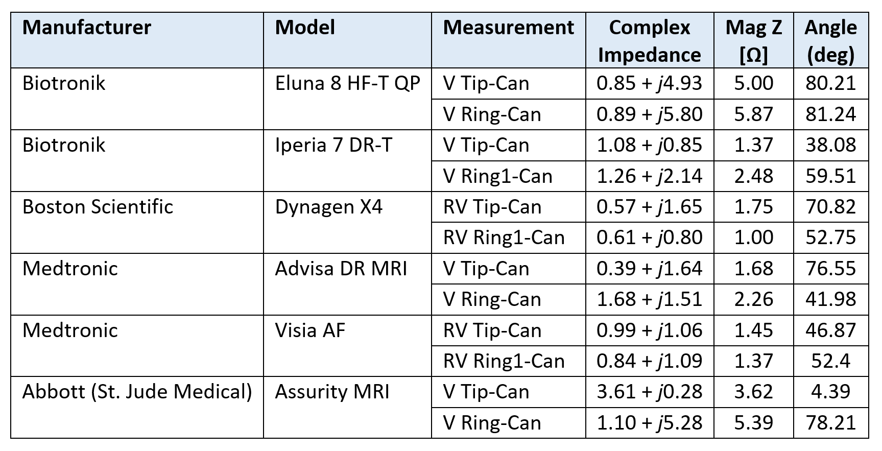
Table 1: IPG input impedance measurement results