2309
Stand-Alone Hardware SAR Monitor based on low cost Electronic Standard Components1Otto-von-Guericke University, Magdeburg, Germany, 2Research Campus STIMULATE, Magdeburg, Germany
Synopsis
A low cost, stand-alone RF power monitor was developed that fulfills the requirements given in the standard 60601-2-33 and is based on electrical standard components. It consists of two dual directional couplers, two RMS envelope filters and a microcontroller. A fixed power limit can be programmed or patient dependent power limits can be communicated from a host computer. Evaluation measurements show power measurement and RFPA blanking switching times accuracies with an error less than 1%. A sampling rate of 130kSamples/s indicates usability for relatively short or moderate complex shaped RF waveforms.
Introduction
Radio frequency (RF) excitation in magnetic resonance (MR) imaging causes residual patient heating due to electric losses in the human tissue [1, 2]. A measure for the absorbed RF energy is the specific absorption rate (SAR), who’s limits are regulated in the standard 60601-2-33 [3]. The compliance of these limits is the central safety mechanism of every patient-rated MR scanner. From the SAR limits, electrical input power limits can be calculated via electromagnetic field simulations [4]. These power limits are measured by a hardware SAR monitor, that blanks the RFPA once power deposition is exceeded. Power meters are usually not freely accessible or applicable to short high power MR RF pulses [5]. Here, a power scalable and low cost hardware SAR power monitor, based on commercially available electrical standard components, is proposed. To demonstrate the functionality and accuracy of the monitor a small scale 1.5T neonate scanner RF chain is used as test environment.Methods
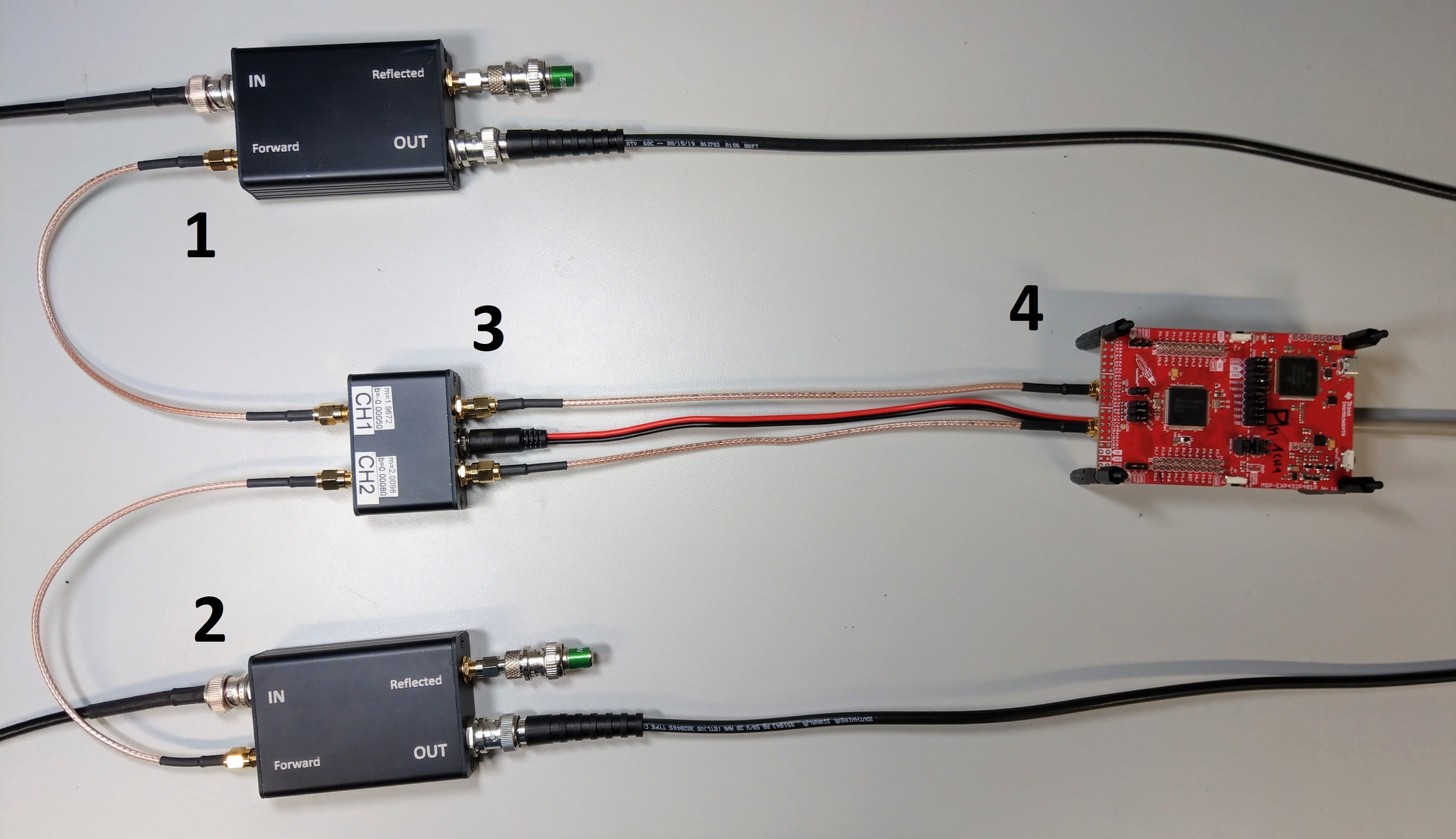
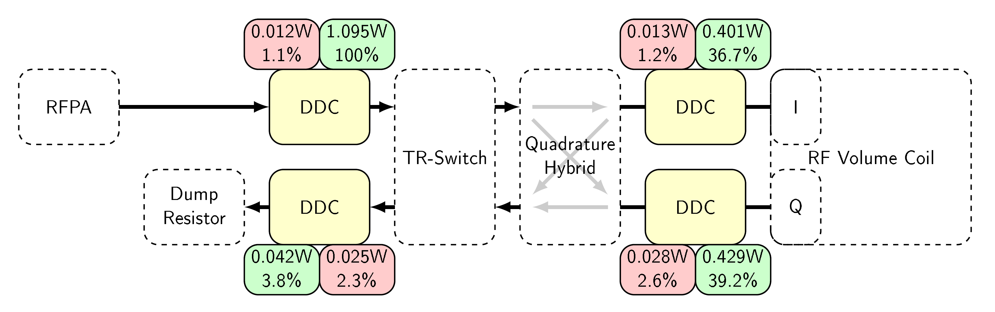
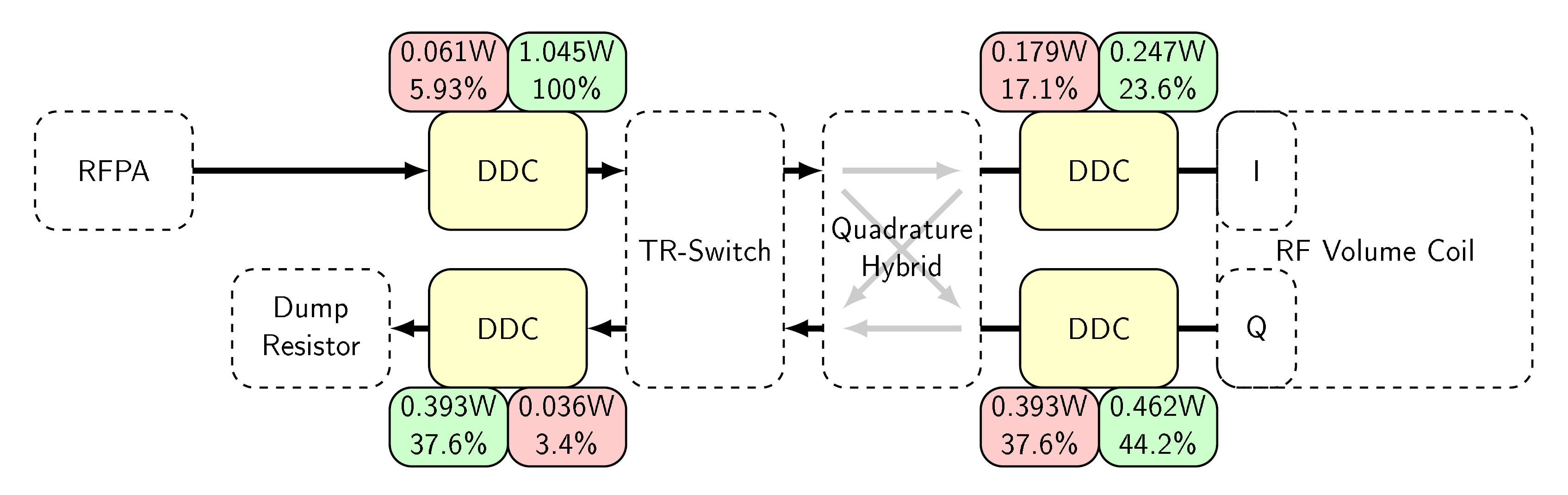
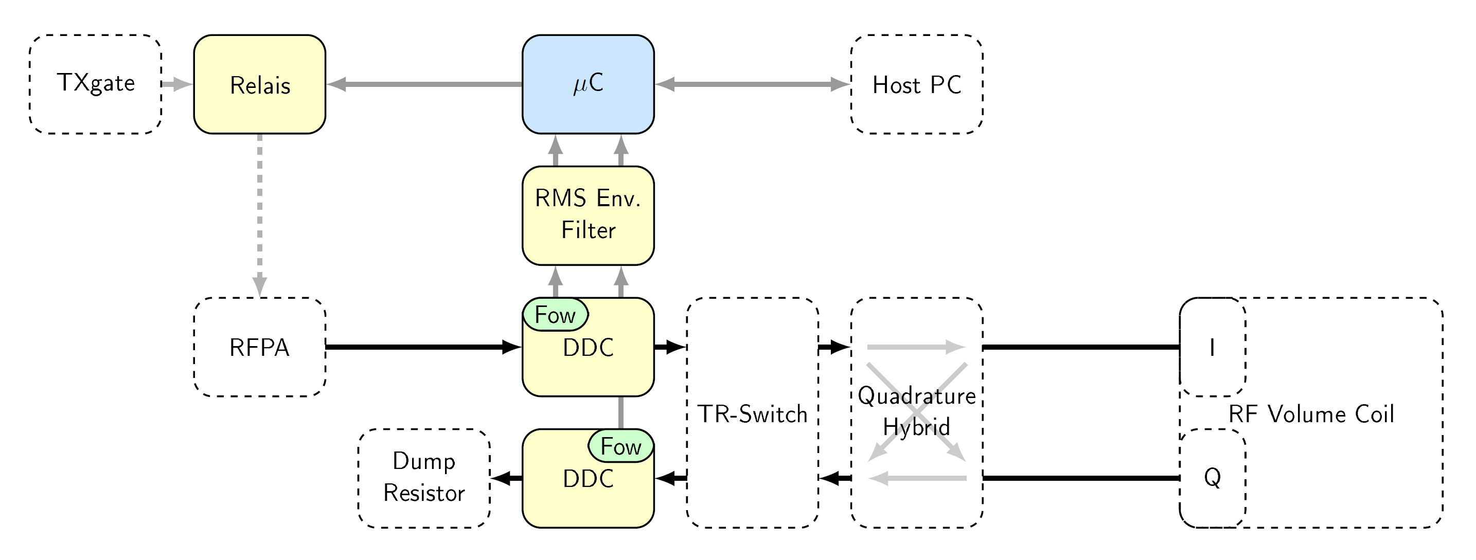
The optimal measuring positions in the excitation RF chain were evaluated. The forward and reflected power distribution of a 1WCW 62MHz signal was measured on the RF chain input, the two RF volume coil ports I and Q, and in front of the reflected power dump resistor using standard SMD dual direction couplers (DDCs) and a spectrum analyzer (Fig. 2). Also a load mismatch was simulated to evaluate the power distribution in case of an RF coil error (Fig. 3).The proposed hardware monitor consists of two DDCs, two RMS envelope filters and a microcontroller (μC) with two analog-to-digital converters (ADCs), an external watchdog and an error state latching logic and RF blanking switch (Fig. 1, Fig. 4). To demonstrate the SAR monitor accuracy and blanking functionality a 100WCW RF signal was applied to the RF chain. The measured power values with the SAR monitor were compared to a spectrum analyzer.
As the SAR limit regulations require 10s and 6min running average surveillance [3], the blanking timing was measured. The stepping for the 10s averaging is programmed on the µC to 40ms and the 6min running average used the 10s means. A fixed power limit can be programmed or patient dependent power limits values, and sampling start, stop or reset commands can be received via a RS232 UART connection from a host computer.
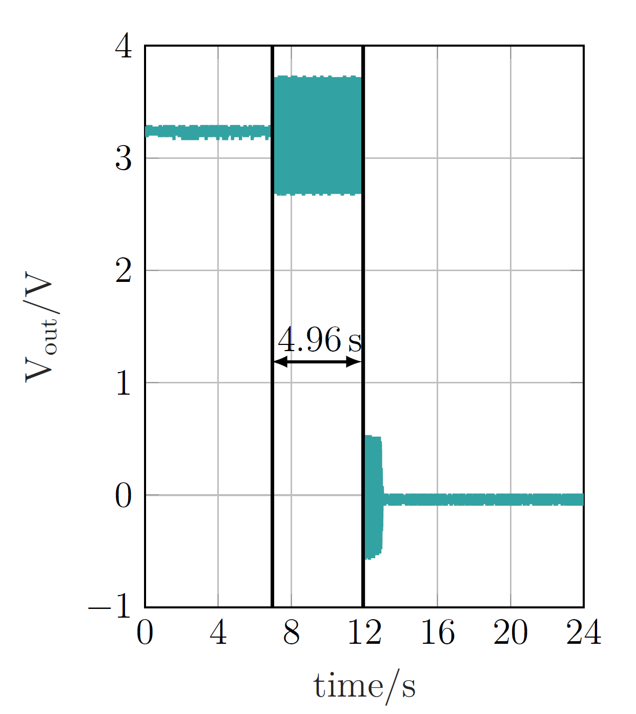
To evaluate the blanking time precision the 10s limit was set to half the previously measured power values, which should result in a RF blanking after exactly 5s.
Results
With enabled RF coil the power distribution (Fig. 2) showed 75.9% (I, Q) of the initial power is transmitted to the RF volume coil. Considering the reflections at the input ports of the coil, 72.1% of the RFPA output power was available for imaging. Only a small portion (3.8%) of the initial power proceeded into the dump resistor. Taking these values, 21.3% was lost in the TR switch and the Quadrature-Hybrid, which generates circular polarization. A mismatched load resulted in a significant change in forward and reflected power (Fig. 3). The main difference was the strong reflection at I and Q with 54.7% and the increase of forward power to 37.7% at the dump resistor.The power measured with the spectrum analyzer was 97.7W and compares to the developed SAR monitor with 96.8W, resulting in a difference of 0.9%.
The sampling rate of the microcontroller was measured with 130kSamples/s.
For the blanking time measurement, the power limit for the 10s running average was set to 48.4W. The limit has been exceeded after 4.96s, which led to the wanted RF blanking with a timing error of only 0.8% (Fig. 5). The oscillation visible in the blanking output signal was due to residual RF coupling into the oscilloscope probes.
Discussion
The power distribution measurement showed that the RF input power is a safe upward approximation of the transmitted RF power at the RF coil and thus the patient. Otherwise it is also possible to calibrate the RF input power to compensate the losses within the transmission line. RF coil mismatches and therefore patient safety relevant errors, can be detected in an increase of RF power to the dump resistor. Therefore, a basic SAR monitor, that handles power limit exceedance and RF coil errors, can consist of a two position RF power monitor at the RF chain input and the power dump resistor.The proposed SAR power monitor based on electronic standard components and a microcontroller can measure high power RF with an error of about 1% compared to a laboratory spectrum analyzer. This precision is only enabled by characterization of all electrical power monitor components by measuring their transfer functions.
A measured sampling rate of 130kSamples/s indicates usability for relatively short or moderate complex shaped RF waveforms.
The RF blanking timing error is 0.8% and within one averaging step (40ms). Only small extra safety margins are necessary to compensate the remaining system errors. The proposed low cost SAR power monitor fulfills the requirements given in the standard 60601-2-33 and enables MR imaging safety surveillance.
Acknowledgements
Parts of this projects are financed from the joint project "F&E RF-System für Neonatale MR-Tomographie" (FKZ: ZS/2018/04/91668) from the EuropeanRegional Development Fund.
The hardware SAR monitor was developed and build in the ego.-Inkubator-"FLEXtronic-Gründungslabor für flexible Elektronik" IK 05/2015 from the EuropeanRegional Development Fund at the Forschungscampus STIMULATE.
References
[1] Zenon Sienkiewicz et al.: “A Closer Look at the Thresholds of Thermal Damage: Workshop Report by an ICNIRP Task Group”. In: Health physics 111 (2016), Nr. 3, S. 300–306. DOI 10.1097/HP.0000000000000539
[2] Zhangwei Wang et al.: “SAR and temperature: simulations and comparison to regulatory limits for MRI”. In: Journal of magnetic resonance imaging : JMRI 26 (2007), Nr. 2, S. 437–441. DOI 10.1002/jmri.20977. – ISSN 1053–1807
[3] International Electrotechnical Commission: Medical electrical equipment – Part 2-33: Particular requirements for the basic safety and essential performance of magnetic resonance equipment for medical diagnosis. 3.2. 2010-03-10
[4] Robert Kowal, Marcus Prier, Enrico Pannicke, Thomas Gerlach, Oliver Speck, Ralf Vick: “Specific absorption rate in dedicated birdcage coil for neonate MRI”. In: ESMRMB 2020 Online, 37th Annual Scientific Meeting, September 30–October 2: Abstracts, Thursday. DOI 10.1007/s10334–020–00874–0, S. 40
[5] Abdel-Monem M. El-Sharkawy et al.: “Accurate Measurement of RF Power Deposition during 3T MRI”. In: Proc Int Soc Magn Reson Med Sci Meet Exhib Int Soc Magn Reson Med Sci Meet Exhib. 2014 (2014)
Figures