2307
RF safety and image quality testing of deep brain stimulation electrodes with 3T MRI1Radiology, Icahn School of Medicine at Mount Sinai, New York, NY, United States, 2Radiology, Mayo Clinic, Rochester, MN, United States, 3Center for Advanced Circuit Therapeutics, Icahn School of Medicine at Mount Sinai, New York, NY, United States, 4Neuroscience, Icahn School of Medicine at Mount Sinai, New York, NY, United States, 5Diagnostic, Molecular and Interventional Radiology, Icahn School of Medicine at Mount Sinai, New York, NY, United States
Synopsis
Radio frequency (RF) safety and image quality testing was performed in the presence of deep brain stimulation (DBS) electrodes using gel acrylamide phantoms and two 3T MRI scanners. Two electrodes, (Abbott and Medtronic) were tested with sequences including GRE, T1-weighted magnetization-prepared rapid gradient echo (MPRAGE), and T2-weighted turbo spin-echo (TSE). Safety testing showed low heating when electrodes were aligned along the B0 field (Z-axis) of the magnet, but higher heating when the electrodes were angled to the main field. Image quality testing showed smaller ferromagnetic susceptibility artifacts when electrode was parallel with B0 field and normal to transmit field.
Introduction
Deep brain stimulation (DBS) has gained interest for treatment of neurological and psychiatric disorders such as epilepsy and depression. Despite increasing clinical evidence for its efficacy, the underlying physiological mechanisms of treatment are less well-understood. Magnetic resonance imaging (MRI) may help elucidate these mechanisms, but scanning patients with implanted ferromagnetic electrodes presents obvious safety and image quality challenges. These challenges are especially salient for diffusion weighted imaging (DWI) and functional MRI (fMRI), which typically necessitate higher field strengths for image quality considerations and whose gradient echo readouts are particularly subject to ferromagnetic susceptibility artifacts. Nevertheless, 3T DWI/fMRI have great potential in identifying changes DBS therapy confers to structural and functional brain networks. This study assesses safety and image quality considerations of scanning with these sequences using DBS electrode on high-field (3T) MRI.Materials & Methods
This study was split into radio frequency (RF) safety and image quality testing conducted across two sites with separate MRIs and two acrylamide gel phantoms. Safety testing was conducted at Mayo Clinic using a GE 3T MRI, ASTM standard phantom[AA1] , body transmit and 32-channel receive head coil. Image quality testing was conducted at the Mount Sinai Hospital with a Siemens Skyra 3T MRI, gel acrylamide phantom molded into a human head shape, and custom 4-channel phased-array surface coil and 15 cm transmit loop coil. Both scanning protocols included T1-weighted MRI, T2-weighted FSE/TSE, 64-direction DWI and resting-state fMRI with 2.0 mm isotropic resolution. DBS leads manufactured by Medtronic (3387) and Abbott (Infinity) were inserted into the ASTM phantom once aligned along the B0 direction (Z-axis) for minimum coupling with the transit fields, and then aligned angled to B0 in a position of high RF coupling. Safety testing was conducted by placing TrueTemp 3.0 fibre-optic temperature sensors at the tip of each electrode and 4 cm away for reference. Temperature was measured every second with a 1-minute pause before initiating each sequence for baseline temperature measurement. Maximum temperature rise from baseline was recorded for each sequence, in both electrodes and in both positions relative to B0. Localized head specific-absorption-rate (SAR) and body SAR were also noted for each sequence. Image quality testing was conducted using the human head phantom and Medtronic DBS electrode placed initially angled and then parallel to the B0 direction, with the transmit loop angled 90° to B0. The physical size of the primary susceptibility artifact around the electrode was measured for each sequence, although minor field effects were visible throughout the field-of-view, particularly in the position of maximum coupling.Results
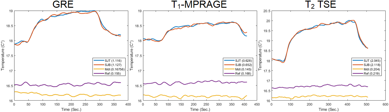
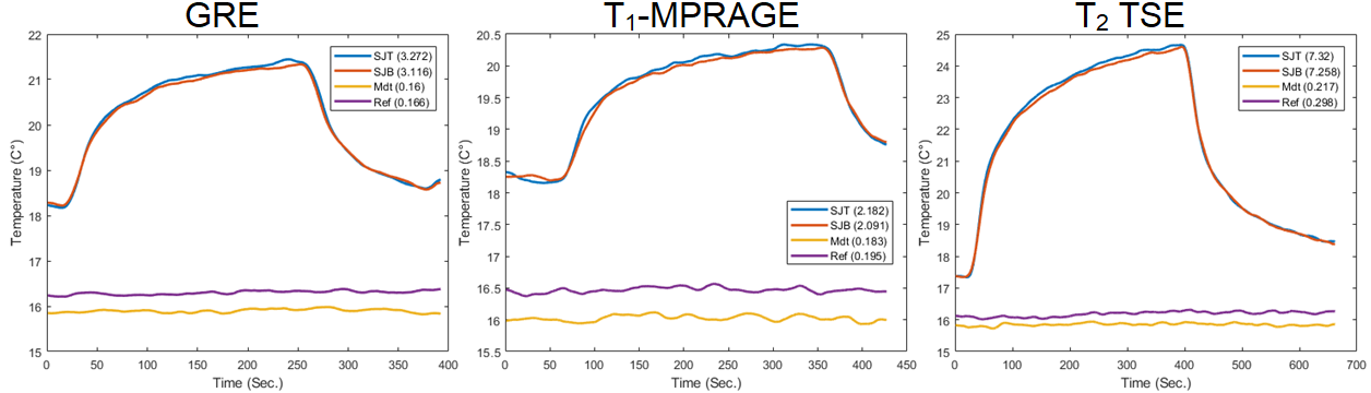
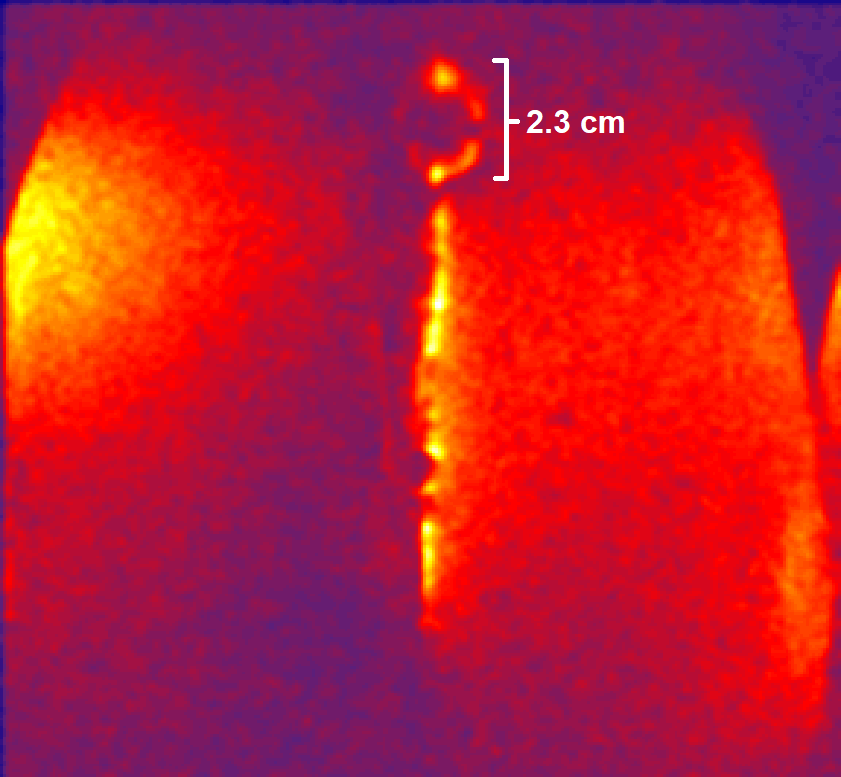
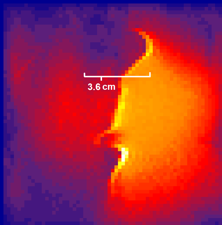
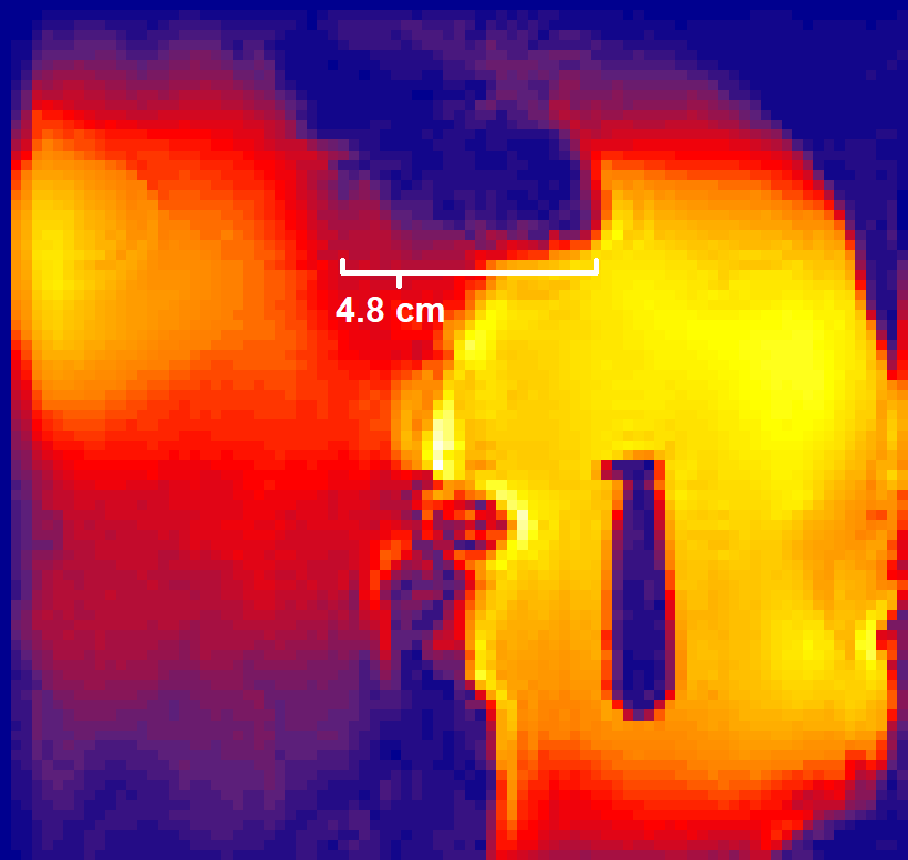
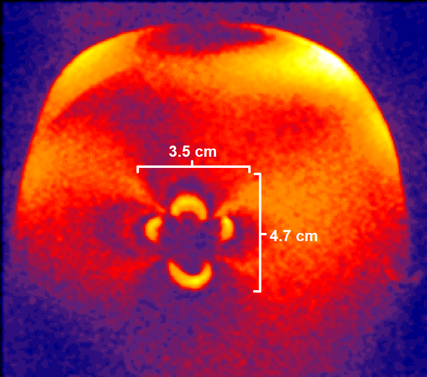
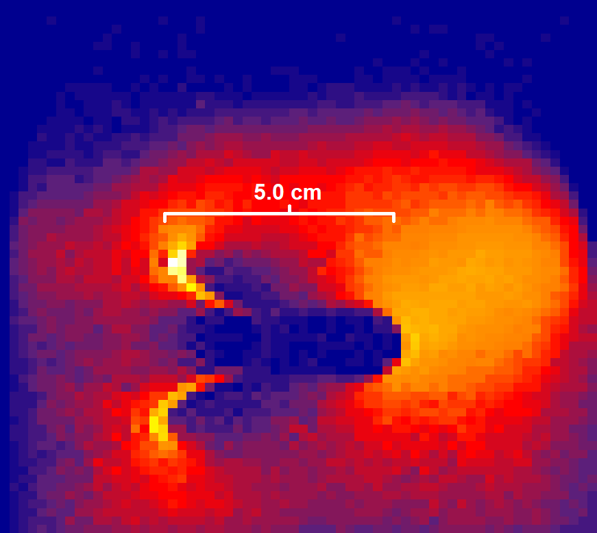
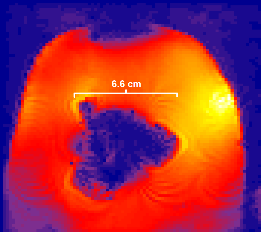
More noticeable heating was observed when the electrodes were angled to the B0 field in a position of strong coupling, though the Medtronic device showed less heating than the Abbott device in our tests. The Medtronic electrode tip heated 0.16 °C with a GRE scan, 0.18 °C with T1-weighted magnetization prepared rapid gradient echo (MPRAGE) and 0.22 °C with the T2-weighted turbo spin-echo (TSE). The Abbott electrode tip heated 3.3 °C with the GRE, 2.2 °C with the T1-weighted MPRAGE and 7.3 °C with the T2-TSE. When aligned parallel to the main field, the Medtronic device heated 0.17 °C with the GRE, 0.15 °C with the T1-weighted MPRAGE and 0.20 °C with the T2-TSE. With the parallel-aligned electrode, the Abbott device heated 1.1 °C with the GRE, 0.63 °C with the T1-weighted MPRAGE and 2.05 °C with the T2-TSE. Image quality testing using the Medtronic device angled to the main field in a position of high coupling with the transmit coil showed a 3.5-4.7 cm wide primary susceptibility artifact under T1-weighted MPRAGE study, 5 cm wide artifact under DWI and 6.6 cm wide artifact with fMRI. When re-scanned with the electrode aligned parallel to the main field, the primary susceptibility was 2.3 cm wide with T1-weighted MPRAGE, 3.6 cm wide with DWI and 4.8 cm wide with fMRI of scans at the tip of the electrode and even narrower across the length of the filament.Discussion
Both safety and image quality testing showed noticeable performance improvements in the sequences when the DBS electrodes were aligned parallel to B0 (Z-axis) and therefore normal to the transmit field (Y-axis). While heating was relatively low with the T1-weighted MPRAGE and GRE studies, specific combinations of poor positioning and material composition can produce RF safety challenges even with these sequences. Though T2-TSE was tested for temperature, it will not be used in in vivo studies for safety reasons.While care was taken to secure the transmit loop such that the transmit field aligned along the y-axis, coupling between the loop and electrode may have been affected by slight shifts in the distance or angle between them. The The DWI and fMRI sequences will be subject to significant susceptibility artifacts, even with favorable positioning, and techniques like local B0 shimming and high readout bandwidths may help address these challenges.
Conclusion
Research into the structural and functional imaging with the implanted DBS lead will face significant challenges related to RF safety and image quality. Positioning the electrode and transmit coil to minimize RF coupling will be an important consideration in overcoming these challenges.Acknowledgements
No acknowledgement found.References
1. ASTM. Measurement of radio frequency induced heating on or near passive implants during magnetic resonance imaging. ASTM F2482‐11a; 2011
2. Riva-Posse, Patricio, et al. "Defining critical white matter pathways mediating successful subcallosal cingulate deep brain stimulation for treatment-resistant depression." Biological psychiatry 76.12 (2014): 963-969.
3. Mayberg, Helen S., et al. "Deep brain stimulation for treatment-resistant depression." Neuron 45.5 (2005): 651-660.
4. Loddenkemper, Tobias, et al. "Deep brain stimulation in epilepsy." Journal of Clinical Neurophysiology 18.6 (2001): 514-532.
Figures