2305
Radiofrequency peak B1+ Survey of commercial 3T MR Systems
Xin Huang1, Vick Chen1, and Shiloh Sison1
1Abbott Laboratories, Sunnyvale, CA, United States
1Abbott Laboratories, Sunnyvale, CA, United States
Synopsis
To determine the appropriate peak B1+ field levels, an RF peak B1+ survey is performed on commercial 3T MR systems loaded with ASTM phantom filled with saline. The peak B1+ averaged over center slab inside the 3T commercial MR systems can be as high as 27 µT. The 3T MRI safety assessment should include values up to this level.
Introduction
High-field MRI such as 3T MR systems provide improved image quality on organs and soft tissue based on a stronger magnet. There is a safety concern of RF-induced voltage damaging active implantable medical devices (AIMDs) or causing unintended stimulation of tissue. The peak B1+ field in the center slab is one of the key factors for MR safety assessment as suggested by ISO/TS 10974:20181. Although the highest B1+ field (peak) currently reported for commercial 1.5 T scanners is 30 μT, this edition does not cover 3T scanners, therefore there is a need to determine the appropriate peak B1+ field levels. In this abstract, an RF peak B1+ Survey was conducted on the commercial 3T MR Systems.Methods
The measurements of RF transmit magnetic field levels are performed in commercial 3T MR systems: Siemens Prisma system and GE MR750 systems. The peak B1+ measurement is evaluated for clinically relevant sequences in each system. In all cases the sequences were taken from the manufacturer’s standard clinical sequence libraries and applied without modification.The ASTM-2009 phantom was used for all testing. The phantom was rectangular with dimensions as defined in ASTM F21822. Testing was conducted with the saline composed to have a conductivity of 0.8 S/m. When used within the GE-MR750 scanner, the saline depth within the phantom was 4.0 cm (larger amounts of saline resulted in a scanner error due to excessive reflected power). For the Siemens Prisma system, the phantom was filled to 7.0 cm at this saline conductivity. In each system, the phantom was positioned such that the middle of the saline volume itself was centered within the scanner (in all directions). The experiment setup is shown in Figure 1.
The TDS H-sniffer probe3 was positioned at the center of the phantom, oriented such that it was sensitive to B1 components in the transverse plane (i.e. the x-y plane). The probe was connected to the Remote Unit, which was in turn connected to an oscilloscope located outside the MR scanner room. The set-up is shown in Figure 2. For any applied RF waveform, the voltage trace on the oscilloscope was captured and the peak observed voltage converted into an equivalent B1 strength. The conversion factor was calculated from the antenna factor of H field sniffer probe provided in the manufacturer’s calibration certificate.
The single point measurement procedure of the B1 waveform was repeated for each pulse sequence, at a set of different orientations of the B1 probe. The probe was rotated through a set of 5 discrete angles with respect to the scanner coordinate system (see Figure 3). The first angle was assigned “0°”. Subsequent angles of 45°, 90°, 135°, and 180° were then separately measured. The measured B1 field is converted into peak B1+ field. The B1+ map sequence was run, which provides the spatial distribution of the B1+ field within the volume of the scanner. The B1+ map is used to convert the isocenter peak B1+ field to peak B1+ slab average as suggested by ISO/TS 10974 ED21.
Results
Across all measurement, the maximum peak B1+ averaged on center slab is 27 µT. The full width of the B1 signal main lobe during this particular acquisition is 130 µs.Discussion
Through the experiment, the maximum peak B1+ averaged over center slab is 27 µT, which results from the 3T Siemens Prisma system during the frequency adjust sequence in pre-scan. Note that the highest peak B1+ for GE is found during the localizer sequence, and it is 53.5% lower than the highest Siemens value.Conclusion
Through experimental measurement in commercial 3T MR systems loaded with an ASTM phantom, the maximum peak B1+ averaged over center slab was found to be 27 µT with a main lobe with 130 µs. This peak value should be considered in RF safety assessment of AIMDs due to hazard of device damage or malfunction and unintended stimulation. This hazard is due to peak voltages applied to the device and can occur with short exposure durations found in pre-scan.Acknowledgements
No acknowledgement found.References
- ISO/TS 10974:2018, Assessment of the safety of magnetic resonance imaging for patients with an active implantable medical device
- ASTM F2182-11a, Standard Test Method for Measurement of Radio Frequency Induced Heating on or Near Passive Implants During Magnetic Resonance Imaging
- TDS H-sniffer probe, https://speag.swiss/products/tds/time-domain-probes/h-field-sni-probes/
Figures
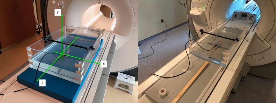
Figure 1. Phantom
used for testing. Left: The phantom is shown filled to a depth of 7 cm for
testing on the Siemens Prisma system. Right: the phantom is shown filled to a
depth of 4 cm for testing on the GE MR750.
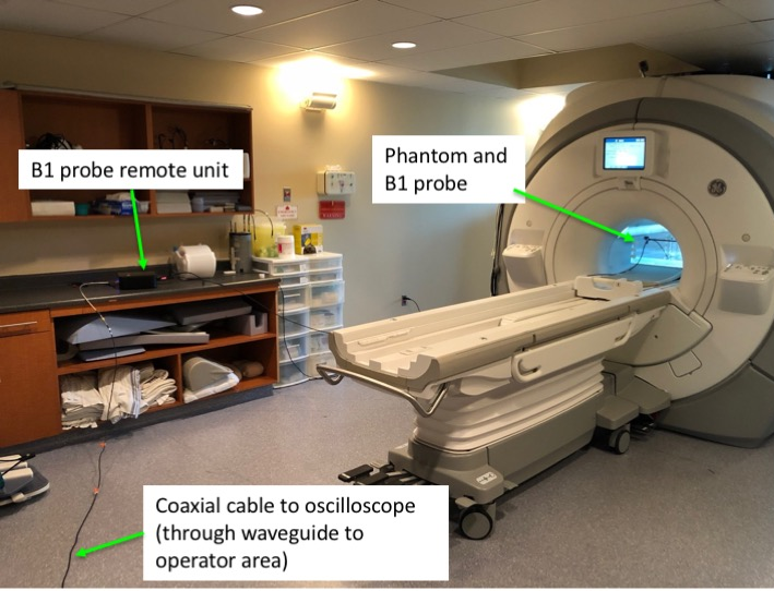
Figure 2. The
general test set-up (GE MR750 testing). The H-field sniffer probe is within the
phantom, in the center of the scanner. The probe remote unit was placed on a
shelf as far away as possible from the scanner. The remote unit was connected,
via a coaxial cable through a waveguide, to a standard oscilloscope positioned
beside the operator console.
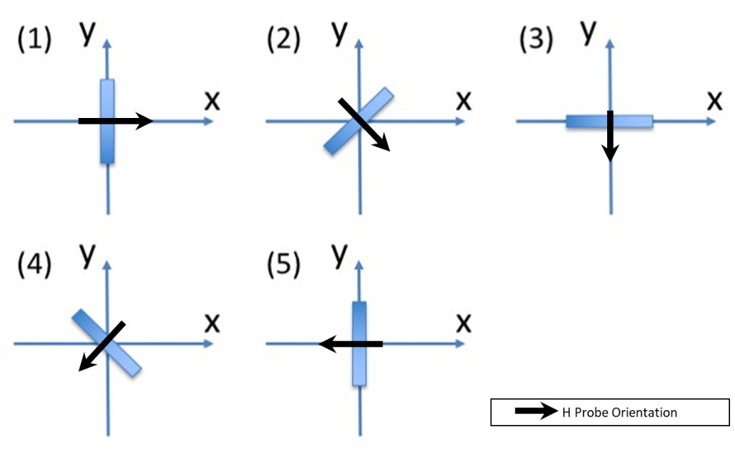
Figure 3. Schematic
of probe orientations. The B1 field was assessed at 5 separate orientations: 1)
0°, 2) 45°,
3) 90°, 4) 135°
and 5) 180°.