2302
Individualized and accurate SAR characterization method based on an equivalent circuit model in MRI system1GE Healthcare, Beijing, China
Synopsis
This work proposed a novel SAR characterization method based on an equivalent circuit model and the circuit’s frequency response analysis. Comparing to well recognized pulse energy method defined in NEMA MS 8, this method doesn’t need the flux loop fixed on transmit coil. Meanwhile, it can monitor SAR accurately. The Root Mean Square (RMS) error and maximum error of the novel method relative to the method in NEMA MS 8 are 4.96% and 9.47% respectively. This method could avoid design complexity of integrating the flux loop and has potential to be easily realized in most MRI scanners.
Introduction
Thermal injury risk introduced by RF field is one of the most concerned bio-effects in MRI scan. To protect patient from RF heating, whole body SAR is the critical value representing the thermal energy absorbed by patients. Especially for the medically diverse patients, such as pregnant women and patients with implant, whole body SAR is required appropriate controlment in MR environment. Currently, commercial MRI scanners usually have relatively large error on SAR monitor, which results in the clinicians and implants manufactories don’t have enough confidence with the scanner reported SAR. Accurate monitor of individualized patient SAR needs extra flux loop installed near body coil according to pulse energy method defined in NEMA MS 8.1 It increases the system design complexity of integrating the flux loop. In this work, we proposed a novel SAR characterization method based on an equivalent circuit model and the circuit’s frequency response analysis. The feasibility and reliability of this method were verified in five volunteers imaged in MRI. Without the flux loop, the monitored whole body SAR shows good accuracy comparing to that monitored by pulse energy method with the flux loop.Methods
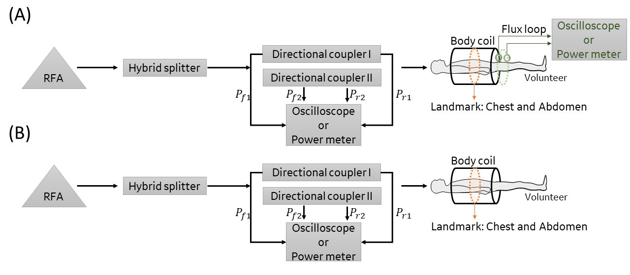
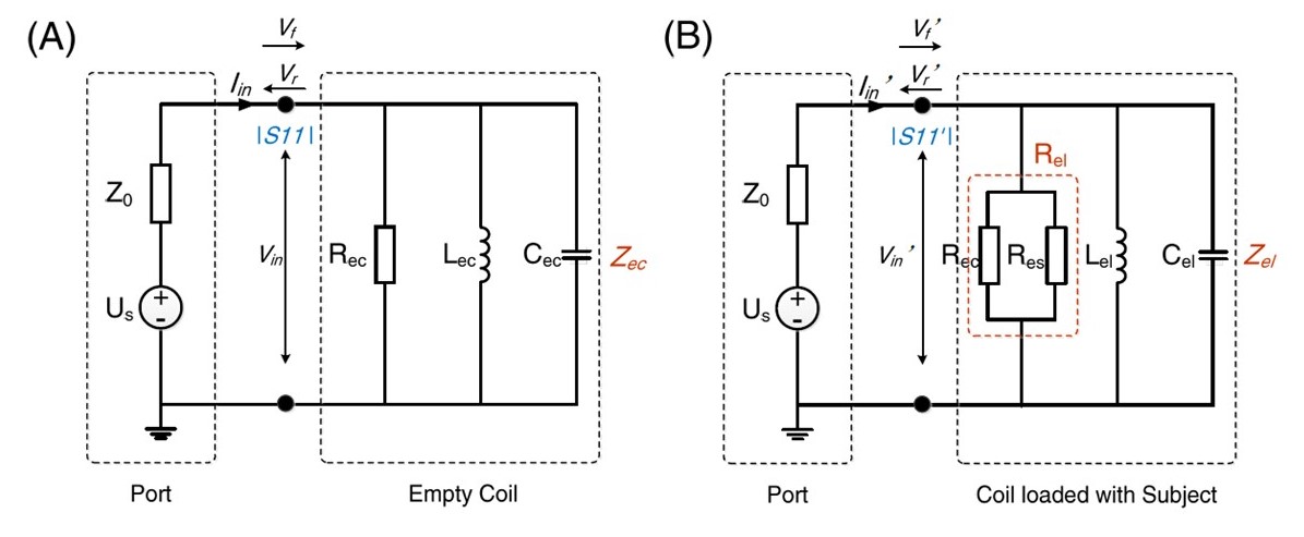
For SAR characterization by pulse energy method with the flux loop, the total RF power transmitted into the coil terminal was measured with directional couplers connecting oscilloscope or power meter, as shown in Figure 1A. Two flux loops connecting oscilloscope or power meter were used to measure the coil absorbed power. Subject absorbed power is equal to the difference between the total power and coil absorbed power. Then subject SAR can be measured.In this work, we used an equivalent parallel circuit model to demonstrate the power distribution principle on the coil and subject.2 Figure 1B shows the experiment setup basing on this model. The flux loop was not needed. Figure 2 illustrates the equivalent circuit model of the coil with and without subject in the body coil. The circuit consists of the power source part and the coil part. For the coil loaded with subject, the RF power absorbed by the coil and subject are dealt with the power deposited on two parallel resistors (Figure 2B). Once the total power absorbed by the coil, coil resistance, and subject resistance are known, the coil and subject absorbed power can be calculated with
$$$P_{coil}=\frac{R_{es}}{R_{ec}+R_{es} }∙P_{total}$$$ (1)
$$$P_{subject}=\frac{R_{ec}}{R_{ec}+R_{es} }∙P_{total}$$$ (2)
Where $$$P_{total}$$$ is the total power absorbed by the coil and subject, $$$P_{coil}$$$ and $$$P_{subject}$$$ are the coil and subject absorbed power, and $$$R_{ec}$$$ and $$$R_{es}$$$ are the coil and subject resistance.
In the experiment setup (Figure1B), $$$P_{total}$$$ is equal to the difference between forward and reflected power, which can be measured with the directional couplers. $$$R_{ec}$$$ and $$$R_{es}$$$ can be fitted with circuit’s frequency response by measuring the power reflection rate at coil terminal for the empty and loaded coil:3
$$$|S11|=|\frac{V_r}{V_f} |=|\frac{√P_r }{√P_f }|=\frac{|R_{ec}-50|}{|R_{ec}+50|} ∙|\frac{cos(atan(\frac{50}{R_{ec}+50 }Q_{ec} (\frac{ω}{ω_0} -\frac{ω_0}{ω})))}{cos(atan(\frac{50}{R_{ec}-50} Q_ec (\frac{ω}{ω_0} -\frac{ω_0}{ω})))}|$$$ (3)
$$$|S11|=|\frac{V_r'}{V_f'} |=|\frac{√P_r'}{√P_f' }|=\frac{|R_{el}-50|}{|R_{el}+50|} ∙|\frac{cos(atan(\frac{50}{R_{el}+50 }Q_{el} (\frac{ω}{ω_0'} -\frac{ω_0'}{ω})))}{cos(atan(\frac{50}{R_{el}-50} Q_el (\frac{ω}{ω_0'} -\frac{ω_0'}{ω})))}|$$$ (4)
Where $$$P_f$$$ and $$$P_f'$$$ are the measured forward power, and $$$P_r$$$ and $$$P_r'$$$ are measured reflected power, at coil terminal for the empty and loaded coil.
With known $$$P_{total}$$$, $$$R_{ec}$$$, and $$$R_{es}$$$, subject absorbed power can be calculated with Equation 2. Subject SAR then can be obtained. According to the circuit theory, the equivalent circuit model is applicable for SAR monitor in a relatively wide RF frequency range near the coil center frequency, in which the power deposited on capacitor and inductor could be ignored.
To verify this method and compare it with pulse energy method, we applied both two methods to five healthy volunteers imaged in compliance with the Institutional Review Board requirements using a body coil at 1.5T scanner (GE, SIGNA Artist).
Results
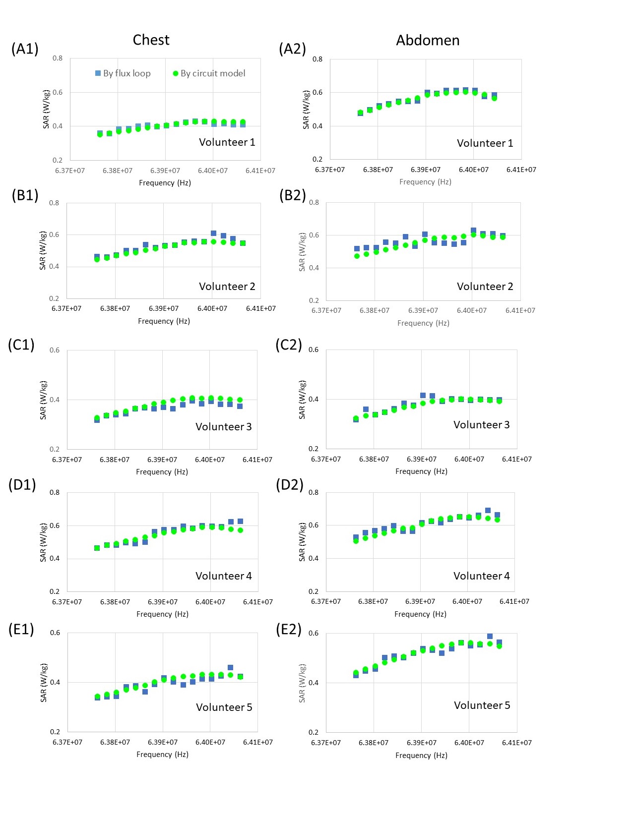
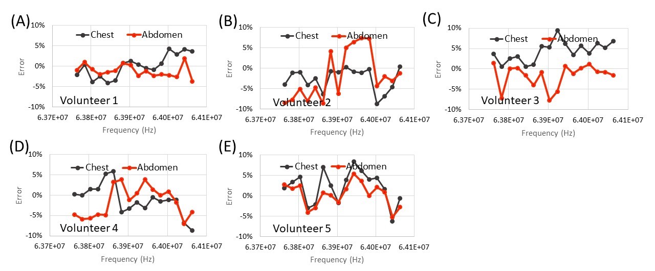
Figure 3 illustrates SAR for the five volunteers landmarked at chest and abdomen, monitored by pulse energy method with the flux loop and equivalent circuit model without the flux loop. SAR in the frequency range of 63.76-64.06 MHz were monitored to verify the applicability of the equivalent circuit model. It is obvious that SAR monitored by the two methods are in good agreement. Figure 4 shows the error of volunteer SAR monitored by the equivalent circuit model, from that monitored by pulse energy method with the flux loop. The error is defined as$$$Err=\frac{SAR_{circuit\,model}-SAR_{flux\,loop}}{SAR_{flux\, loop}} $$$ (5)
For the scanned volunteers, the RMS error and maximum error are 4.96% and 9.47% respectively.
Discussion
This work proposed a novel accurate method to individualized monitor the whole body SAR. A parallel RLC circuit model was used to reveal well the power distribution on the subject and coil during MRI scan. The subject in a coil was treated as a resistor paralleled with the coil’s equivalent resistor. By measuring the frequency response of the power reflection rate at the coil terminal for empty and load coil, the equivalent resistance of the coil and subject can be fitted. And the fraction of the subject absorbed power in the total power transmitted into the coil was determined. By measuring the total power with directional couplers connecting oscilloscope (or power meter), the subject absorbed power and the subject SAR can be determined easily.Acknowledgements
No acknowledgement found.References
1. National Electrical Manufacturers Association.: NEMA Standards Publication MS 8 – 2016: Characterization of the Specific Absorption Rate for Magnetic Resonance Imaging Systems. National Electrical Manufactures Association, Rosslyn, Virginia, USA (2016).
2. Smith K.C.A., Alley R.E.. Electrical circuit theory. Cambridge University Press, 1992, page 164-166.
3. Joel P.D.. Handbook microwave component measurements with advanced VNA techniques. John Wiley & Sons, Inc., 2020, page 4-11.
Figures