2299
Patient specific parallel transmit pulses are patient position dependent while safety models are fixed: safety implications1CUBRIC, School of Psychology, Cardiff University, Cardiff, United Kingdom
Synopsis
Pulses designed using patient-specific B1+-maps are inherently patient position dependent, while safety models (available on scanners) used for local SAR supervision are not. The effect of this positional mismatch on SAR estimation was investigated for 1-/2-/3-/4-/5-spoke pulses. The results showed substantial underestimation of local SAR: the actual local SAR at off-centre positions was observed to be up to 4.6-fold higher compared to the peak estimated using a centred model. This behaviour was worse for more spokes and consistent across slices between cerebellum and crown. Using multiple distributed models reduced the likelihood of SAR underestimation, but at the cost of over-restrictiveness.
Introduction
Individual differences in head shape and size, variations in padding material options within and across scanners, and circumstantial adjustments (e.g. extra padding to reduce discomfort) lead to variations in patient positioning. Virtual observation points1 or Q-matrices2 are often provided with parallel transmit (pTx) radiofrequency (RF) coils to enable local specifical absorption rate (SAR) supervision. However, these safety models -whether generated at one or multiple positions- are insensitive to the current patient positioning. On the contrary, patient specific RF pulses are designed using B1+-sensitivity maps that are position dependent. This study investigates the effect of this positional mismatch between safety models and B1+-maps on local SAR estimation.Methods
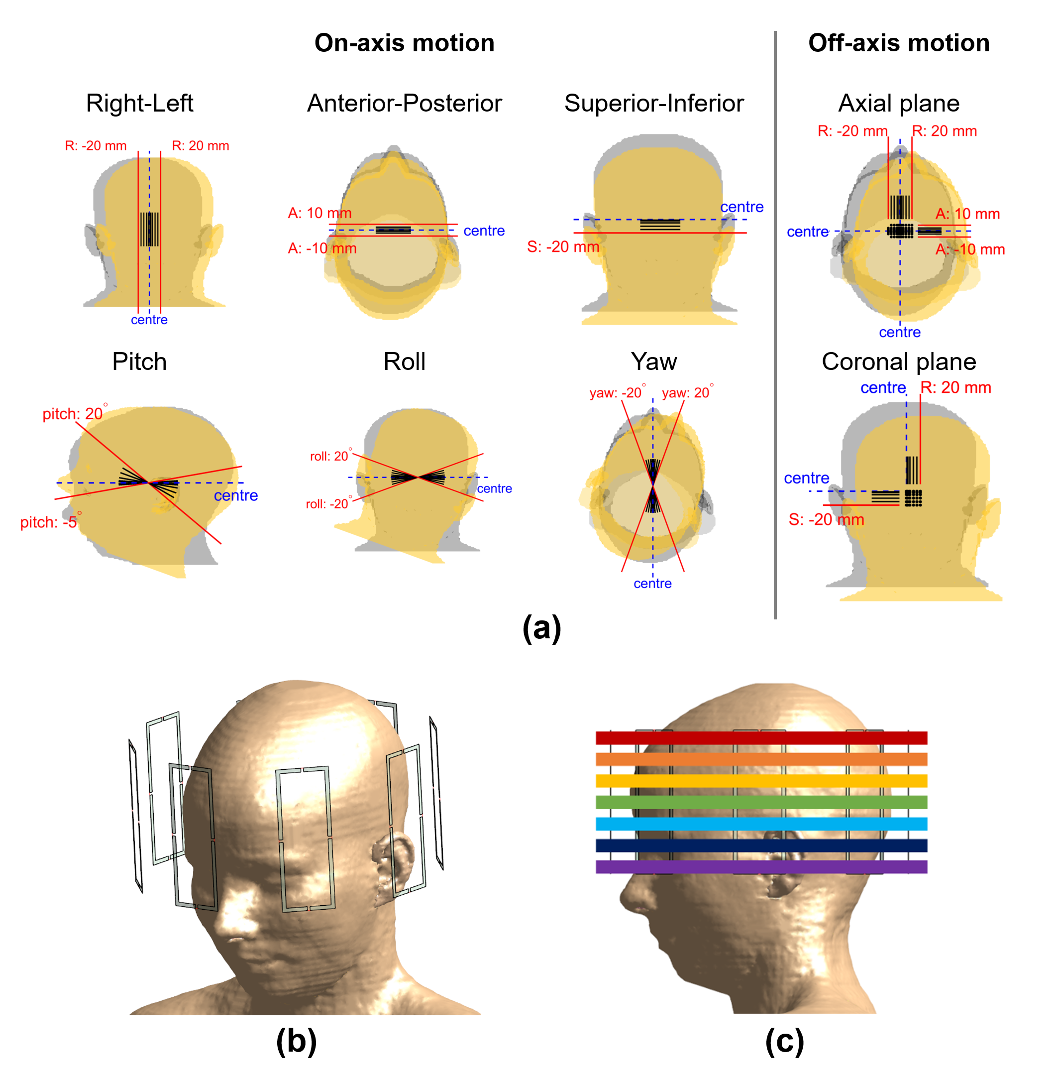
Electromagnetic (EM) simulations were performed using Sim4Life (ZMT, Zurich, Switzerland) using the virtual body model Ella3 for 163 different relative positions of the body model with respect to the 8-channel generic coil structure (Figure 1). These included on/around axis displacements/rotations of 1/2/5/10/15/20 mm/degrees and off-axis displacements (axial/coronal planes). Cases (in axial, pitch) that would overlap coil elements and the model were excluded.Entries of the Q-matrices2 were averaged over 10-grams of tissue with cubical volumes4. Small-tip-angle 1-/2-/3-/4-/5-spokes pulses were designed using Matching Pursuit guided Conjugate Gradient5,6 for seven slices (from cerebellum to crown) at each position – yielding 5705 pulses. Channel coefficients were re-optimized with the addition of each spoke. The peak spatial (local) SAR (psSAR) of each pulse was evaluated using the body models
- (i) at the position the pulse was designed for (psSAR-actual),
- (ii) at centre (psSAR-centre),
- (iii) at centre and A=±5mm, A=±10mm, R=±5mm, R=±10mm and highest was used (9 models; psSAR-9positions).
Results
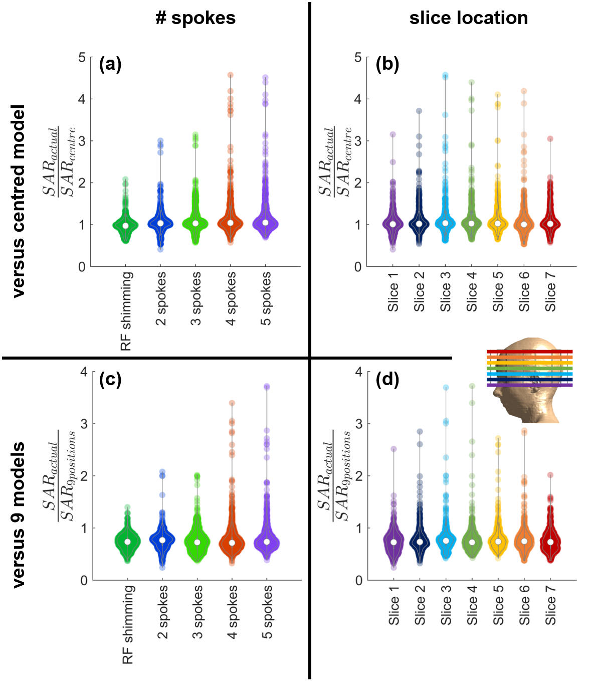
Positional mismatch between the B1+-maps used for pulse design and Q-matrices used for safety evaluations led to up to 78% underestimation of peak local SAR. The sensitivity of SAR to positional mismatch increased with increasing pulse complexity. Actual SAR was up to 2.1-fold higher than the estimated peak for RF shimming (1-spoke) and 4.6-fold higher for 4-/5-spokes pulses (Figure 2a-b).The sensitivity of local SAR to positional mismatch was not specific to any part of the brain (Figure 2b). Two-sample t-test comparison of slices showed insignificant variation in 15 of 21 comparisons.
Using 9 body models to calculate psSAR reduced the positional mismatch sensitivity (Figure 2c-d). Nevertheless, the actual psSAR was still up to 3.7-fold higher than the estimate.
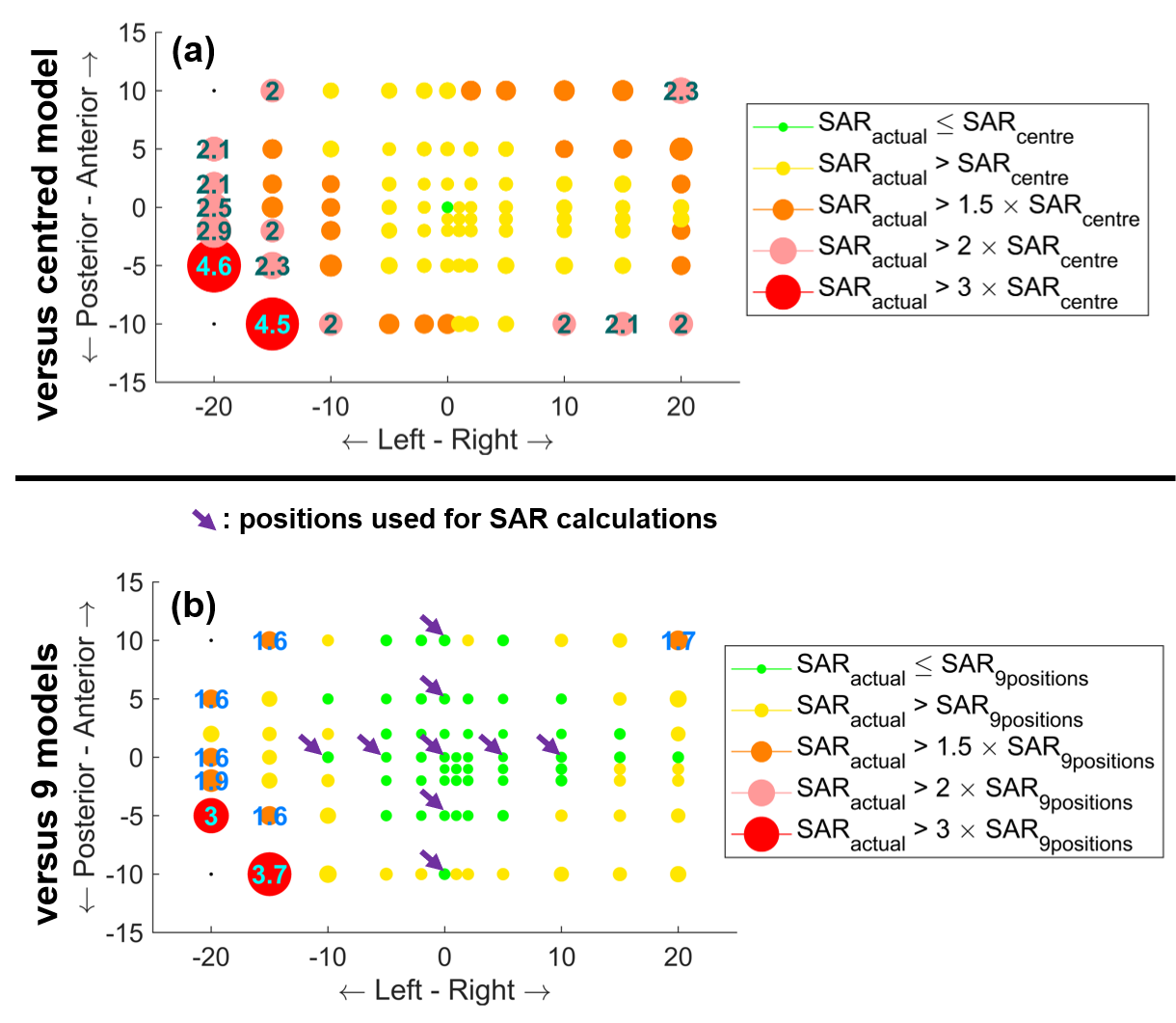
Figure 3 shows the maximum sensitivity of local SAR to positional mismatch across slices and spokes at each axial position (rotations and coronal results omitted here). Actual SAR exceeded the estimate at all positions, and by more than 50% at 40% of the positions. Using 9 models (arrows) to estimate psSAR benefitted the majority of positions close to these positions. However, this benefit comes at the cost of over-conservative SAR estimations: the peak local SAR of pulses designed for the centred position was overestimated by 54% with these 9 models.
Figure 3 is the maximum intensity projection across spokes and slices. Therefore, the effect of using 9 models varies across positions; i.e. the worst-case of 4.5 was for 4 spokes (panel-a) whereas 3.7 was for 5 spokes (panel-b). Hence, SAR reduction varies spatially.
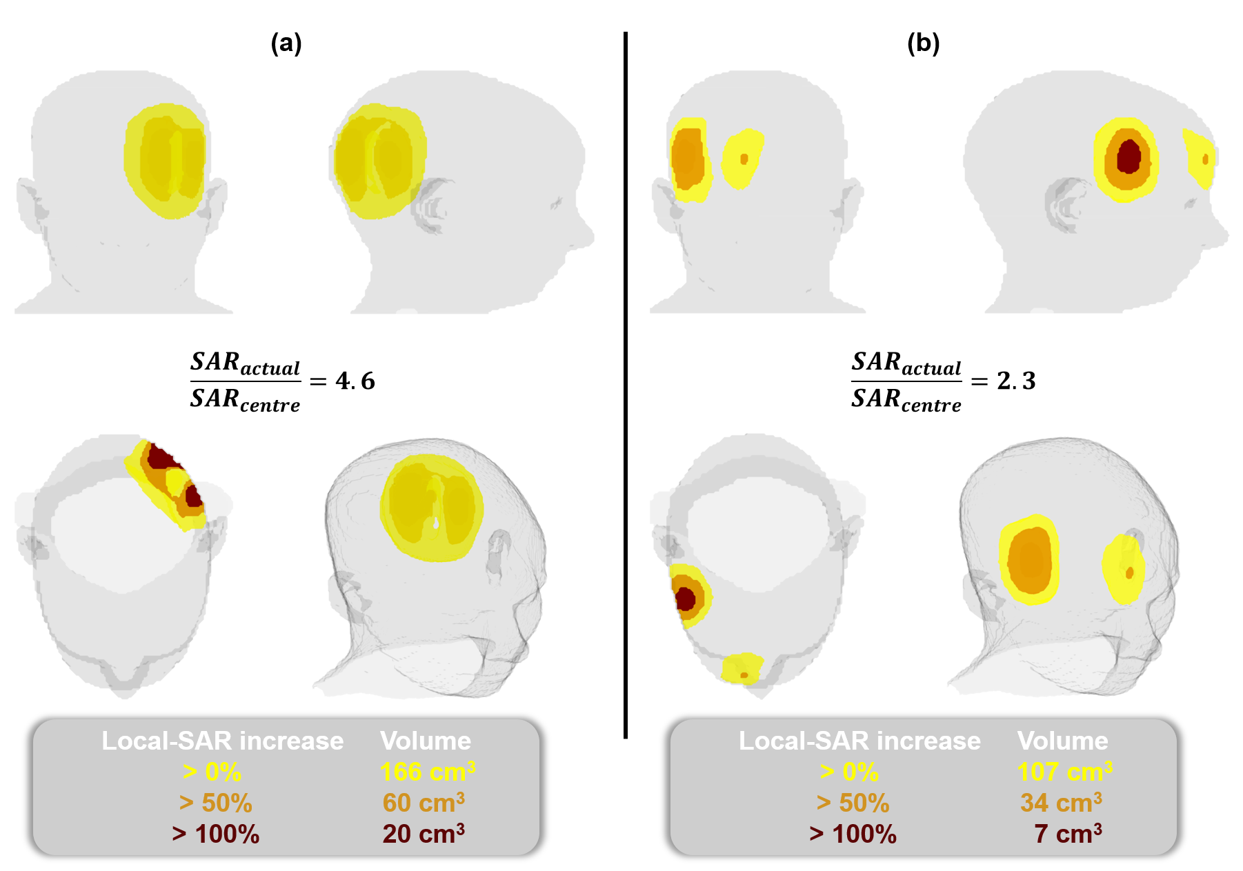
The actual local SAR was 4.6-fold as high as the estimate and a region of 20 cm3 was exposed to more than twice the estimated peak at the worst case (Figure 4a). Figure 4b shows another case where the right-anterior part of the head observes actual local SAR greater than SAR-centre.
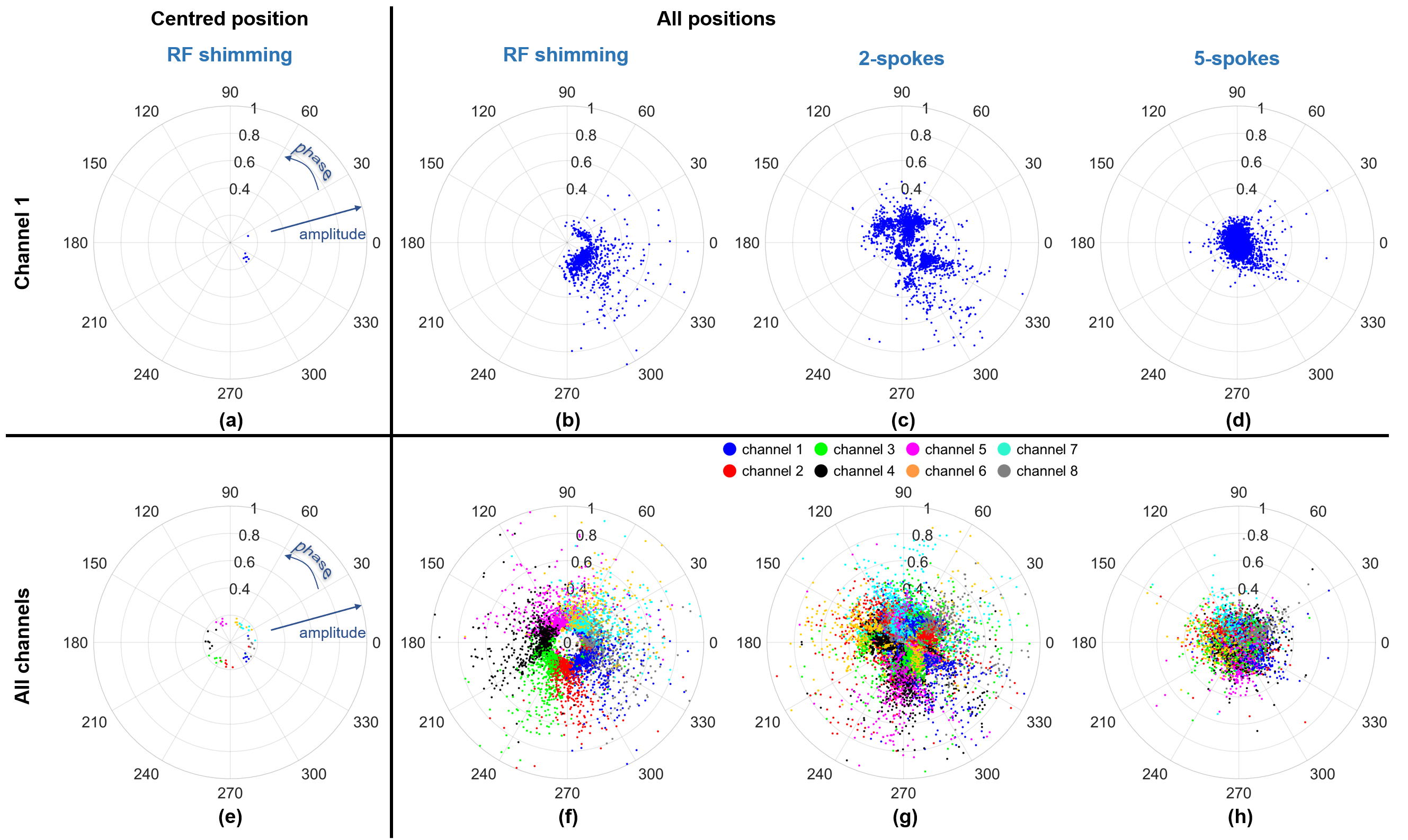
As the pulse gets more complex (more spokes), the sensitivity of SAR to positional mismatch increases. This is attributed to the much higher variation in coil coefficients for more spokes (Figure 5). For RF shimming at the centred position, all coils have minimal variation in amplitude and well-defined phase “zones” across the slices. Therefore, the SAR-related interaction between coil elements will vary less. When all positions are investigated though, the variation in amplitude increases substantially while the phase “zones” remain intact. When more spokes are added, the “zones” diffuse; and coil coefficients and consequently SAR patterns become more varied across positions, leading to unpredictable SAR-actual/SAR-centre behaviour.
Discussion
Patient specific pulses use B1+-maps that are inherently position dependent. However, scanners/coils have fixed safety models. This creates potential safety hazards as positional mismatches lead to up to 4.6-fold higher actual SAR than the estimated peak.Using more models reduces the risk of exceeding the estimates and using all positions would minimize it. However, much like using maximum eigenvalues being over-conservative6, this solution would be over-conservative (>4.6 safety margin implied here) to the degree that would outweigh the benefit of parallel-transmit. Calculating the SAR of a pulse designed for R:-20mm A:-5mm at the opposite corner R:20mm A:10mm would likely yield even a higher ratio, unnecessarily constraining SAR even further for an unrealistic scenario. A feasible approach might be to estimate the position of a participant (e.g. via localizer images) and use the models/positions that closely enclose the estimated position to ensure safety while minimizing over-estimation. This can also be extended to real-time adjustment of safety models in case of motion6.
Acknowledgements
No acknowledgement found.References
1. Eichfelder G, Gebhardt M. Local specific absorption rate control for parallel transmission by virtual observation points. Magn Reson Med 2011;66(5):1468-1476.
2. Graesslin I, Homann H, Biederer S, Börnert P, Nehrke K, Vernickel P, Mens G, Harvey P, Katscher U. A specific absorption rate prediction concept for parallel transmission MR. Magn Reson Med 2012;68(5):1664-1674.
3. Christ A, Kainz W, Hahn EG, Honegger K, Zefferer M, Neufeld E, Rascher W, Janka R, Bautz W, Chen J, Kiefer B, Schmitt P, Hollenbach H-P, Shen J, Oberle M, Szczerba D, Kam A, Guag JW, Kuster N. The Virtual Family—development of surface-based anatomical models of two adults and two children for dosimetric simulations. Physics in Medicine & Biology 2010;55(2):N23.
4. IEC/IEEE International Standard -- Determining the peak spatial-average specific absorption rate (SAR) in the human body from wireless communications devices, 30 MHz to 6 GHz - Part 1: General requirements for using the finite-difference time-domain (FDTD) method for SAR calculations. IEC/IEEE 62704-1:2017 2017:1-86.
5. Kopanoglu E, Constable RT. Radiofrequency pulse design using nonlinear gradient magnetic fields. Magn Reson Med 2015;74(3):826-839.
6. Kopanoglu E, Deniz CM, Erturk MA, Wise RG. Specific absorption rate implications of within-scan patient head motion for ultra-high field MRI. Magn Reson Med 2020;84(5):2724-2738.
Figures