2298
Compact 3T MRI for patients with implanted devices: Software tool to display MR fields at a specified location
Lydia Jean Bardwell Speltz1,2, Yunhong Shu2, Myung-Ho In2, Nolan Meyer1,2, Erin Gray2, Diana Lanners2, Yihe Hua3, Robert E Watson2, John Huston III2, Thomas KF Foo3, and Matt A Bernstein2
1Mayo Clinic Graduate School of Biomedical Sciences, Mayo Clinic, Rochester, MN, United States, 2Department of Radiology, Mayo Clinic, Rochester, MN, United States, 3GE Global Research, Niskayuna, NY, United States
1Mayo Clinic Graduate School of Biomedical Sciences, Mayo Clinic, Rochester, MN, United States, 2Department of Radiology, Mayo Clinic, Rochester, MN, United States, 3GE Global Research, Niskayuna, NY, United States
Synopsis
Many implanted devices are labeled MR Conditional, meaning specific, labeled conditions must be met to ensure safe scanning. We developed a software tool for use with a high-performance, compact 3T (C3T) scanner that verifies relevant MR conditions can be met at the location of the device (e.g., abdomen), even if those conditions are exceeded at the level of the anatomy being scanned (e.g., brain). MR parameters assessed include main magnetic field strength, gradient slew rate, RF amplitude (B1+2), and dB/dz. The limited extent of the fields with C3T suggests high-performance exams can sometimes be obtained without compromising patient safety.
Introduction
Many patients undergoing MRI exams have MR conditional implanted devices. These devices can be safely imaged under specified MR conditions. Commonly-imposed conditions1,2 include: maximal main magnetic field strength (B0), maximal spatial gradient dB/dz, maximal SAR or B1+rms, maximal gradient slew rate, and the type of RF transmit coil (e.g., no restriction, or restricted to a transmit/receive head or extremity coil).The compact 3T (C3T) scanner was developed under NIH funding as a technology demonstrator3. Its small size enables high-performance gradients: simultaneous slew rate of 700T/m/s and gradient amplitude of 80mT/m with a higher peripheral nerve stimulation threshold than whole-body gradients4. The gradient coil has an inner diameter of 42cm, allowing for exams of the head, extremities and infants. Because brain and knee exams are common, these cover approximately 45% of all clinical exams at our institution.
Because of the smaller scanner size, the patient is only partially inserted into the scanner bore. Consequently, labeled MR conditions can be met at the location of the implanted device (e.g., the lumbar region) even if the conditions are greatly exceeded at the location of the imaged anatomy (e.g., the brain). Spatial maps of B0 and dB/dz5, RF amplitude (i.e., B1+)6, and slew rate7 have been previously reported. In this work the measurements were augmented, and we report a tool developed to conveniently display the spatial dependence of relevant electromagnetic fields, and to determine whether the MR conditions of specific devices are met at the location of interest.
Methods
A THM1176-HF Teslameter [MetroLab, Washington, DC] was used to extend the previously-measured main magnetic field values. Zero-field calibration was performed before each testing session. The following main magnetic field strengths were measured: 3T, 2.75T, 2.6T, 2.5T, 2.4T, 2.25T, 2T, 1.75T, 1.6T, 1.5T, 1.4T, 1.25T, 1T, 0.8T, 0.6T, 0.4T, 0.2T. Each of these field strengths was measured in the physical X-direction in five 5cm increments and in the physical Y-direction in six 6.5cm increments about isocenter for a total of 510 measurements. Previously-reported measurements of gradient slew rate, B1+, and dB/dz were integrated to develop a device assessment tool using MATLAB [MathWorks, Natick MA]. MR conditions for devices were obtained from manufacturer’s package inserts, which are available on their websites or in curated form at MR safely information websites (e.g., MagResource8). Inputs to the proposed tool are the device’s location in three Cartesian coordinates relative to scanning isocenter, and the patient orientation and anatomic region being scanned (head-first brain, feet-first knee, or feet-first foot/ankle).An IRB-approved protocol enables subject recruitment for this study. The proposed tool’s use is illustrated considering a brain scan for a patient implanted with a Senza implanted pulse generator (IPG) [Nevro, Redwood City CA], part of a spinal cord stimulation system to treat chronic leg and back pain. Specific conditions for this device include: main magnetic field strength of either 1.5T or 3T and at 3T: no body transmit (or any RF transmit placed over the device), maximum spatial field gradient of 19T/m or less, gradient slew rate of 200T/m/s per axis or less9.
Results
Figure 1 illustrates a device location (ΔS/I=-60cm, ΔA/P=-5cm, ΔR/L=-5cm) from isocenter as a red circle for persons of three different heights for a head-first brain exam. Note that the input coordinates may need to be re-entered to match the actual device location as determined by an x-ray, palpitation, etc., and patient height. The main magnetic field strength and normalized (B1+)2 are shown in Figure 2. Consistent with the plot, a value (B1+)2 = 0.2087% (or B1+=4.6%) of its maximum value at isocenter. The rapid falloff of B1+ produced by the head RF transmit coil shown implies the condition is met. Figure 3 shows the spatial dependence of the maximum gradient amplitude for each physical gradient coil. The maximum slew rates follow the same spatial contours on each corresponding axis7. Finally, the value of dB/dz appears in the MATLAB command window based on device location. In this example, the interpolated value of dB/dz at the location of the device is 7.30T/m.Discussion and Conclusion
This study demonstrates how the tool can help ensure conditions of a MR conditional implanted device can be satisfied at the location of the device, even if they are exceeded at the location of the anatomy being scanned. In this example, all four conditions for the Senza IPG can be met. The main magnetic field strength at the device location was below the limit (Figure 2a). The maximum slew rate and spatial field gradient were less than 200T/m/s and 19T/m, respectively (Figure 3). Additionally, the RF was negligible at the device location because the transmit coil’s field covers the head (Figure 2b) and rapidly diminishes to a negligible level inferior to the clavicles. This could allow for the use of a multi (e.g., 32)-channel receive head coil, rather than single-channel T/R head coil. Compared to a whole-body scanner, substantial improvement in image quality would be expected on the C3T due to the benefits offered by multi-channel brain coil, parallel imaging techniques, increased slew rate, or other factors.Acknowledgements
This work was supported by research grant: NIH R01EB010065 and U01 EB024450.References
- ACR MR Safety Guidance document; https://www.acr.org/-/media/ACR/Files/Radiology-Safety/MR-Safety/Manual-on-MR-Safety.pdf accessed 15 Dec 2020.
- ACR Committee on MR Safety:, Greenberg TD, Hoff MN, Gilk TB, et al. ACR guidance document on MR safe practices: Updates and critical information 2019. J Magn Reson Imaging. 2020 Feb;51(2):331-338. doi: 10.1002/jmri.26880. Epub 2019 Jul 29. PMID: 31355502.
- Foo TKF, Laskaris E, Vermilyea M, et al. Lightweight, compact, and high performance 3T MR system for imaging the brain and extremities, Magn Reson Med 2018 80, 2232-2245.
- In MH, Shu Y, Trzasko JD, et al. Reducing PNS with minimal performance penalties via simple pulse sequence modifications on a high-performance compact 3T scanner. Phys Med Biol. 2020 Jul 31;65(15):15NT02. doi: 10.1088/1361-6560/ab99e2. PMID: 32503007; PMCID: PMC7571537.
- Shu Y, Tao S, Vermilyea M, et al. Static magnetic field (B0) gradient evaluation of a compact 3T MR scanner. Proceedings of the 2017 International Society for Magnetic Resonance in Medicine Annual Meeting.
- Shu Y, Meyer NK, Bardwell LJ, et al. Compact 3T MRI for imaging patients with implanted devices: RF and SAR considerations. Proceedings of the 2019 International Society for Magnetic Resonance in Medicine Annual Meeting.
- Bernstein MA, Edmonson HA, Hua Y, et al. Compact 3T MRI for imaging patients with implanted devices: Maximum gradient slew rate considerations. Proceedings of the 2019 International Society for Magnetic Resonance in Medicine Annual Meeting.
- Magresource website; http://www.doctordoctor.biz/search/Login.aspx accessed 11 Dec 2018.
- NERVO CORP. (2020, June 22). 1.5 Tesla and 3 Tesla Magnetic Resonance Imaging (MRI) Guidelines for the SENZA, SENZA II & SENZA Omnia Systems (IPG1000, IPG1500, IPG2000 and IPG2500). Magresource. https://www.doctordoctor.biz/PDF/Nevro/Senza.pdf
Figures
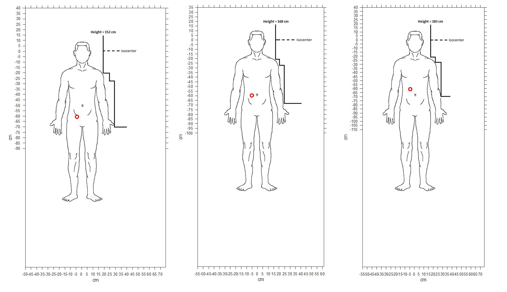
Figure 1: Senza IPG location based on three different heights indicated
as a red circle.
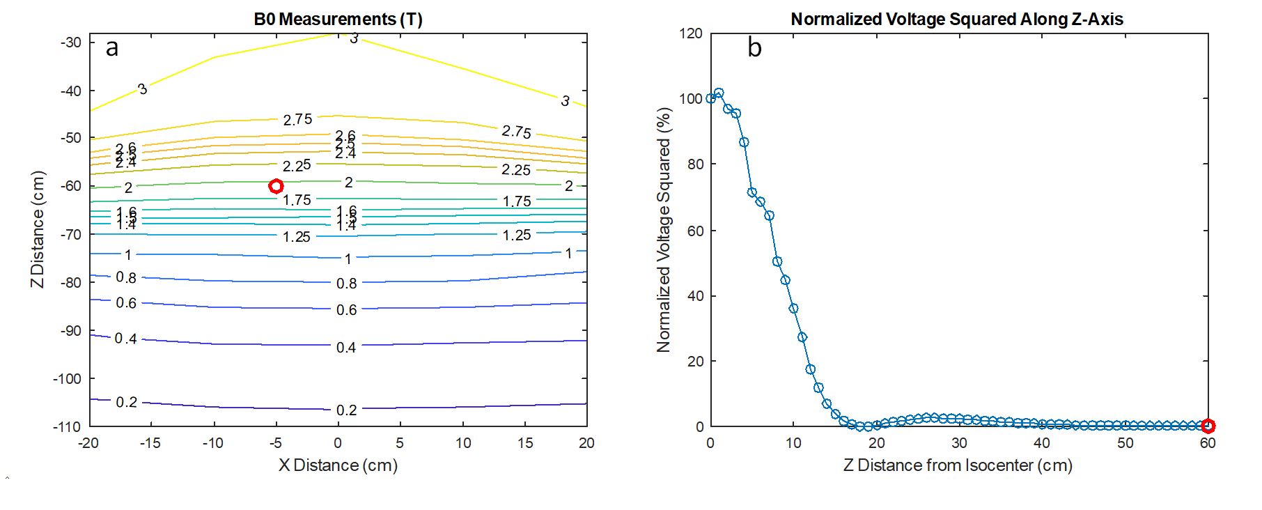
Figure 2: For
the specified location of the device (red circle), shown are a) the main
magnetic field strength and b) normalized RF voltage squared along the z-axis,
which is a measure of (B1+)2. Because the RF is negligible at the
location of the device, even if the device labeling calls for a T/R head coil, the
brain could be scanned with a multi-channel receive head coil, which offers a
substantial improvement in image quality.
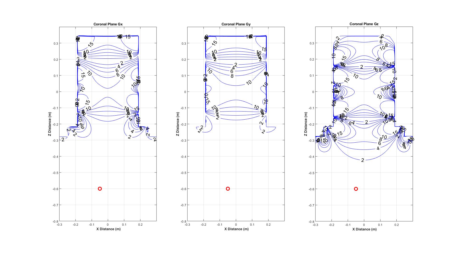
Figure 3: Contour
plots for the gradient amplitude calculated for the three gradient axes within
the scanner dimensions. The maximum slew rates follow the
same spatial contours on each corresponding axis7. At isocenter, each maximum gradient amplitude
is normalized to a value of 10mT/m. This means a labeled maximum slew rate of
200T/m/s corresponds to a value of 2.8mT/m on the plot, because the maximum
slew rate for the compact 3T is 700T/m/s. The red circle again shows the location of the
device.