2290
Lead electromagnetic models for RF-induced heating in multi-electrode cortical implants1Magnetic Resonance Institute for Safety, Technology and Research GmbH, Gelsenkirchen, Germany, 2MR:comp GmbH, Testing Services for MR Safety & Compatibility, Gelsenkirchen, Germany
Synopsis
This work focus on estimating the RF-induced deposited power at the multi-electrode array of cortical implant (CorTec GmbH, Germany) by means of lead electromagnetic models (LEM). To develop the LEM for such a complex structure, we computed the transfer function for each of the electrode and generated a set of artificial tangential electric fields for validation of the LEM. The transfer functions and the tangential electric fields along the leads are then used to develop the LEM which can estimate the deposited power at the electrode array for an arbitrary lead pathway.
Introduction
Cortical implants significantly improves the quality of the life of the patients with neurological disorder by restoring or replacing certain circuitry of the brain which no longer functions properly. These implants, however, may cause thermal hotspots in the brain during an MRI examination and, therefore, require a thorough investigation concerning MRI safety and compatibility.To assess the RF-induced heating at a hotspot, the medical implants are often simulated to observe their electromagnetic behavior under high frequency radio waves. However, a complete 3D electromagnetic simulation of a sophisticated implant with long leads is often too time consuming and require extensive computing resources. In such cases, the transfer function approach along with the lead electromagnetic model (LEM) is employed to estimate the magnitude of the electric field around the electrodes. Further, the LEMs provide a possibility to estimate the radio frequency (RF) induced heating of an implant for an arbitrary trajectory of the implant’s geometry. Therefore, the objective of this work is to compute the transfer functions and validate the lead electromagnetic models for the cortical implant developed by CorTec (CorTec GmbH, Germany) with 1x4 multi-electrode arrays. The developed LEM would be able to predict the net incident electric field around electrodes for any potential lead pathway.
The lead electromagnetic models as described in ISO/TS 109741 comprise of a transfer function of the implant, tangential electric field along the lead pathway and a constant. The LEM is given by
$$~~~~~~~~~~P_{lem} = A \left| \int_0^l S(l) E_{tan}(l)dl \right|^2. ~~~~~~~~~~~~~~~~~~~~~~~~~~~~~~~~~~~~~~~~~~~~~~~~~~(1)$$
Here, $$$S(l)$$$ is the transfer function, $$$E_{tan}(l)$$$ is the tangential electric field along the lead pathway, $$$A$$$ is the calibration factor, and $$$l$$$ is the length of the lead. Moreover, the RF-induced net incident power in a tissue due to the presence of a medical implant can be computed using direct simulations as2
$$~~~~~~P = \int^V \sigma \left( \left| E_{lead}(v) \right|^2 - \left| E(v) \right|^2 \right) dv, ~~~~~~~~~~~~~~~~~~~~~~~~~~~~~~~~~~~~~~~~(2)$$
where, $$$E_{lead}(v)$$$ and $$$E(v)$$$ are the electric fields with and without the lead, respectively, $$$\sigma$$$ is the conductivity of the surrounding medium, and $$$V$$$ is the hotspot integrating volume (HSIV).
Methods
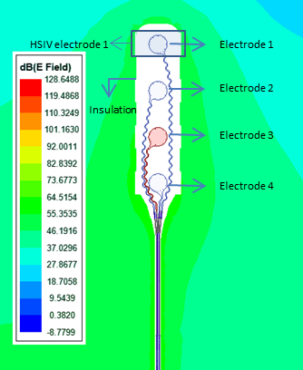
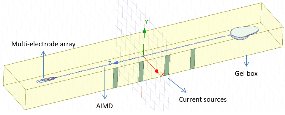
The CorTec's cortical implant considered in this study consists of a 45cm long lead which is composed of four copper wires. Each wire has a diameter of 0.15mm without insulation and 0.17mm with insulation and is connected to a zig-zag structured electrode (Fig. 1). All four wires are bound together with a large silicone insulation of 1mm diameter and the whole lead is further covered with silicone insulation of dimeter 1.4mm. The transfer functions of all four leads are computed by using reciprocity method3. Further, the transfer functions are computed using ANSYS HFSS (ANSYS Electromagnetics 2020 R1) at resonance frequency of 64MHz with leads being inserted in gel medium with physical properties defined as per ASTM standard4.To validate the LEM, an artificial set of tangential electric fields are generated by four power sources located on one side of the gel box. All other walls of the box are taken to be the perfect matching layer boundaries. A set of 40 artificial electric fields are generated by randomly choosing magnitude and phase of the power sources (Fig. 2). Once an electric field is generated, its tangential component ($$$E_{tan}(l)$$$) is computed along the lead pathway. This tangential field along the lead and the transfer function are then substituted in Eq. (1) to compute the LEM response without the constant A as,
$$~~~~~x_{i} = \left| \int_0^l S(l) E_{tan,i}(l)dl \right|^2, i \in \{1,2, \cdots, 40 \} ~~~~~~~~~~~~~~~~~~~~~~~~~~~~~~~ (3)$$
Further, the incident net power in the HSIV is calculated directly from electromagnetic simulations using Eq. (2) which is then used in linear regression along with Eq. (3) to calibrate the constant A.
Results and Discussion
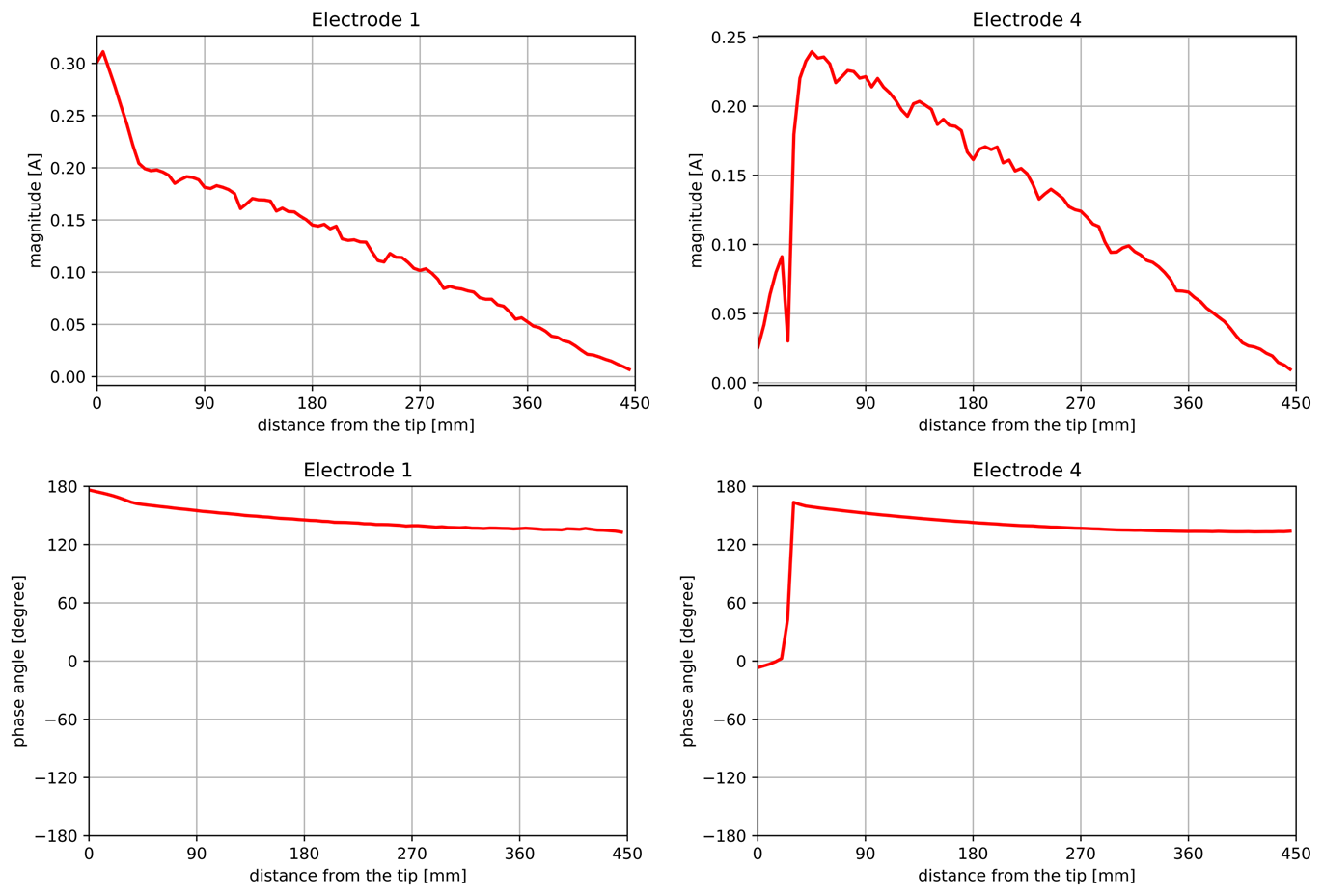
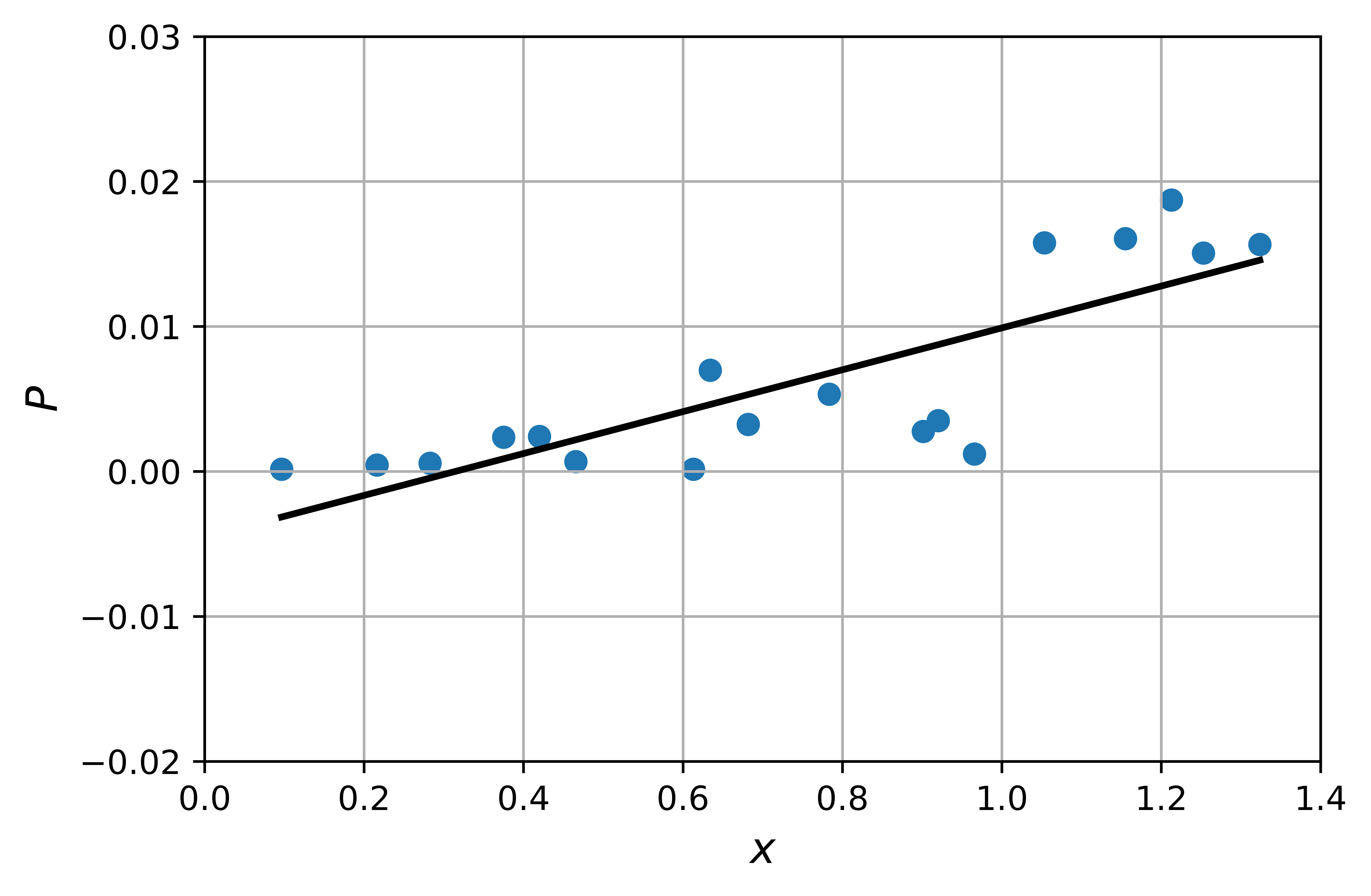
We computed the transfer function and validated the LEM for all four electrodes. Fig. (3) shows the magnitude and phase of the transfer functions computed for the electrodes 1 and 4. $$$S(l)$$$ shows a significant dependence of the position of the electrode with respect to the other electrodes. This means that induced current in the neighboring wires and electrodes have an effect on the RF response of the investigated electrode. Further, since the distance among the wires are very small and remains constant along the lead pathway, the transfer functions are computed by estimating the total current flowing in all wires rather than computing current in the single wire whose electrode is excited by the current source5.The linear regression fit gives a reasonable match for all the lead electromagnetic models. Fig. (4) shows the linear fit for the LEM of electrode 1. Some numerical noise is expected because of the complex structure of the electrodes and the approximations made in numerical integration. The linear fit, however, catches the overall trend in the increasing behavior of LEM well.
Conclusion
The developed lead electromagnetic model is validated using linear regression approach and is generic in nature. The model can be used on arbitrary lead pathway to estimate the RF-induced heating due to the cortical implant with 1x4 multi-electrode array.Acknowledgements
We acknowledge the financial support provided by BMBF (Federal Ministry of Education and Research, Germany) for this project (Lightbridge, Grant 16ES0787).References
[1]. ISO/TS 10974: Assessment of the safety of magnetic resonance imaging for patients with an active implantable medical device," International Organization for Standardization, Geneva, Switzerland; 2018.
[2]. M. Kozlov, M. Horner and W. Kainzs. Modeling radiofrequency responses of realistic multi‑electrode leads containing helical and straight wires, Magnetic Resonance Materials in Physics, Biology and Medicine, 33(3): 421-437, 2020.
[3]. S. Feng, R. Qiang, W. Kainz, and J. Chen. A technique to evaluate mri-induced electric fields at the ends of practical implanted lead. IEEE Transactions on microwave theory and techniques, 63:305–313, 2015.
[4]. ASTM standard F 2182-2011a, 2011. ASTM 2182 Standard test method for measurement of radio frequency induced heating near passive implants during magnetic resonance imaging. ASTM Int. 1–14
[5]. J. Kabil, J. Felblinger, P. Vuissoz and A. Missoffe. Coupled transfer function model for the evaluation of implanted cables safety in MRI, Magnetic Resonance in Medicine, 00:1-9, 2020
Figures