2281
RF Impedance of MR-Conditional Pacemaker Leads when Connected to Implantable Pulse Generators from Different MR-Conditional Systems
David Prutchi1, Jason Meyers1, and Ramez Shehada2
1Impulse Dynamics (USA) Inc., Marlton, NJ, United States, 2Medical Technology Laboratories, La Mirada, CA, United States
1Impulse Dynamics (USA) Inc., Marlton, NJ, United States, 2Medical Technology Laboratories, La Mirada, CA, United States
Synopsis
RF-induced heating of an active implantable medical device (AIMD) composed of a pulse generator (IPG) and leads depends on the transmission line impedance of the lead and its proximal-end termination by the impedance of the IPG. We demonstrate that the RF impedance of IPGs is minimal relative to that of the leads, which dominates the overall impedance of the implantable system. Accordingly, mixed hybrid systems composed of MR-Conditional leads and any MR-conditional IPG are expected to have a comparable overall impedance and consequently produce the same RF-induced heating as their corresponding original systems specified by the manufacturers.
Introduction
MR-conditional active implantable medical devices (AIMDs) composed of an implantable pulse generator (IPG) and leads are deemed to be MRI-safe only when used in specific IPG-leads combinations that have been jointly tested for RF-induced heating by their manufacturer. This is because the RF-induced heating at the lead electrodes depends on the transmission line impedance characteristics of the lead and its proximal-end termination by the impedance of the IPG. The RF impedance characteristics of the IPG-leads combination determines how induced RF currents get transmitted to the tip of the lead to cause heating at the electrode-tissue interface. Accordingly, mixing MR-conditional IPGs and MR-conditional leads from different manufacturers do not guarantee the MR-conditional safety of their combination as an implantable system. The current regulatory stance is that an implanted system comprised of the IPG of one manufacturer does not fulfill the requirements of MR-conditional labeling if used with the leads from a different manufacturer. In this study we measured and compared the RF impedances of various MR-conditional IPGs and leads from different manufacturers to determine the impact of mixing these components on the overall RF impedance and consequently assess the RF safety of the hybrid implantable system.Methods
The RF input impedance for several MR-conditional cardiac leads and IPGs were measured and compared to evaluate their relative contribution to the overall RF impedance of potential hybrid systems that can be formed from mixed combination these leads and IPGs. The RF-induced heating safety of the aforementioned hybrid systems was assessed by comparing their RF impedances to that of corresponding original systems specified by the manufacturers.Results and Discussion
Table 1 and Figure 1 compare the contribution of the input impedance of various MR-conditional IPGs against the total lead/IPG impedance to 63.87 MHz RF currents at the Tip (distal) electrode when paired with lead models that are MR-conditional labeled for whole-body MRI at 1.5T.For these comparisons, lead impedance data which incorporates the effect of the implantable device’s enclosure in gel slurry1 was used since it represents the worst-case condition. As shown, the lead is overwhelmingly responsible for limiting 63.87 MHz RF currents from flowing through the Tip electrode in an implanted system. The IPG’s contribution to the limitation of RF currents is relatively small (range of 1.03 to 8.04%, mean 2.72%).
Table 2 presents the worst-case IPG contributions to the total lead/IPG impedance to 63.87 MHz RF currents at the lead’s Tip electrode with different IPG/lead combinations. Whenever two IPGs were evaluated for the same leads, the lowest IPG input impedance was used to be representative of the worst-case condition.
The minimum contribution (0.98%) to total impedance happens when the Medtronic CapsureFix 5076 52 cm lead is connected to the Biotronik Iperia IPG. However, the contribution of the Medtronic Visia IPG with the same lead in a configuration labeled as MR-conditional is 1.03%, which is a difference of barely -4.85%. This is probably negligible when compared to possible changes in lead impedance as a function of water content, medium conductivity, aging, etc.
Conclusions
For all the IPGs and leads studied, the IPG input impedance is relatively negligible compared to the lead’s impedance and hence can be considered as a short circuit at the 1.5 T MRI frequency of 63.87 MHz. Because the input impedances of the IPGs are all relatively low, a system composed of any of the studied IPGs and any of the transvenous leads approved as MR-conditional will have very similar RF impedance to a system composed of an MR-conditional labeled IPG and the same lead, and therefore both systems are expected to exhibit similar RF-induced electrode heating behavior.Acknowledgements
This work was supported by Impulse Dynamics (USA) Inc.References
- Meyers J, Prutchi D, Shehada R, Input Impedance Comparison of MR-Conditional Cardiac Implantable Pulse Generators at the 1.5T MR Frequency of 63.87 MHz , Submitted to ISMRM 2021
- Prutchi D, Meyers J, Shehada R, Impedance of MR-Conditional Pacemaker Leads at the 1.5T MR Frequency of 63.87 MHz, Submitted to ISMRM 2021
Figures
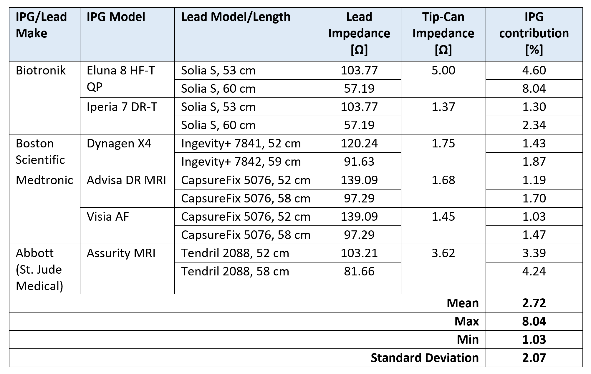
Table 1: Contribution of
IPG input impedance against the total lead/IPG impedance to 63.87 MHz RF
currents at the lead’s Tip electrode.
Lead impedance incorporates the effect of the implantable device’s
enclosure in gel slurry. Lead/IPG pairs are MR-conditional labeled for
whole-body MRI at 1.5T.
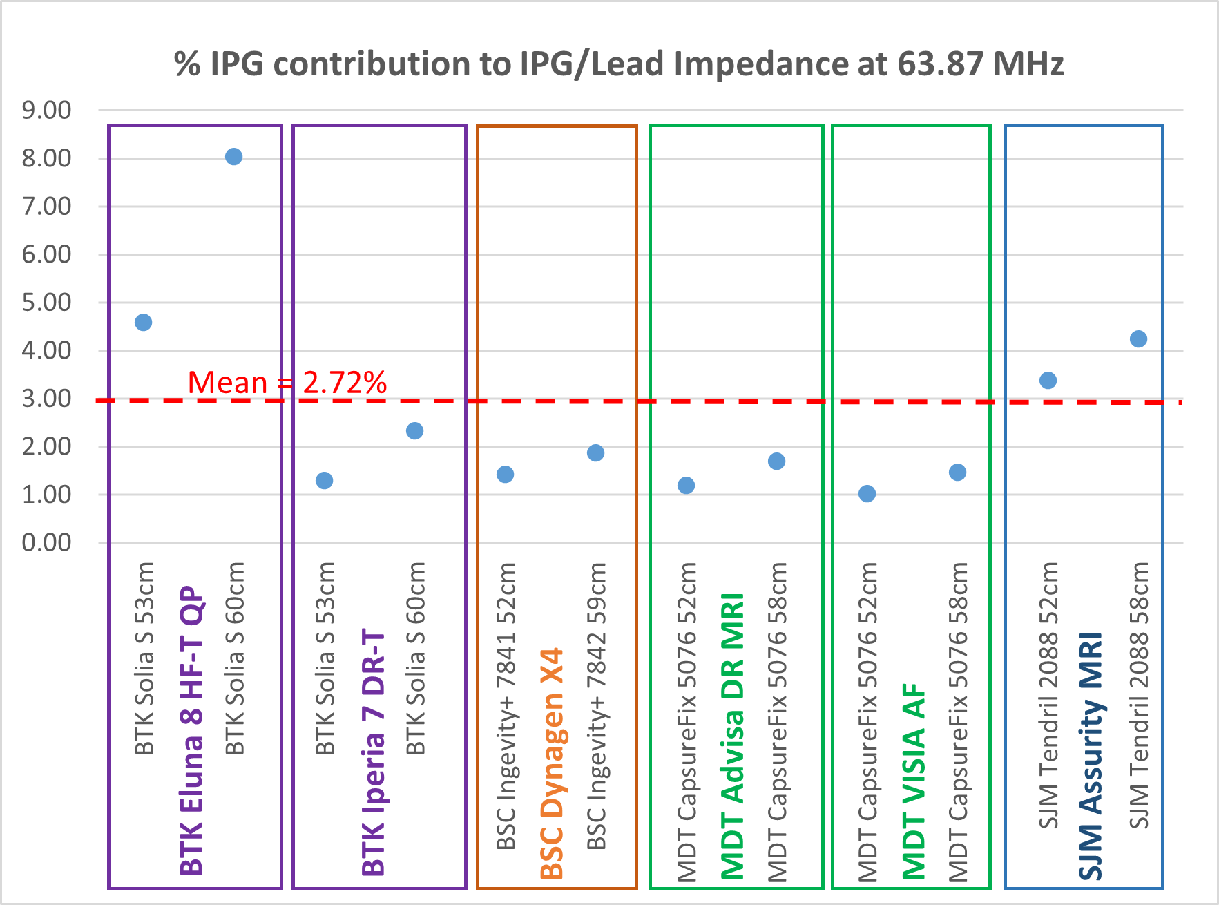
Figure 1: Contribution of IPG input
impedance against the total lead/IPG impedance to 63.87 MHz RF currents at the
lead’s Tip electrode. Lead/IPG pairs are
MR-conditional labeled for whole-body MRI at 1.5T.
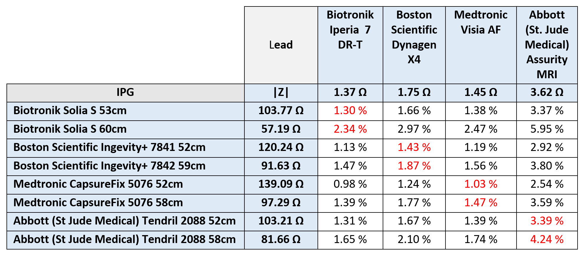
Table 2: Worst-case contribution of
IPG input impedance against the total lead/IPG impedance
to 63.87 MHz RF currents at the lead’s Tip electrode with different IPG/lead combinations. Items marked in red correspond to the
combination labeled as MR-conditional.