2280
RF-Induced Heating of Medical Devices in an Open Bore MRI1MED Institute Inc., West Lafayette, IN, United States
Synopsis
The goal of this study was to develop a computational model that can accurately predict the radiofrequency (RF) induced temperature rise of medical devices in a 1.2T (49 MHz) Hitachi Oasis open bore system for the purpose of MRI labeling according to ASTM F2503. A comparison of experimental and analytical temperature rise of calibration rods, a stent, and a knee implant within a gel phantom was conducted. Simulations of RF heating of the stent and knee implant within the Duke virtual human model were compared for the 1.2T Hitachi Oasis open bore and 1.5T Siemens Avanto closed bore MRI systems.
Purpose
Open bore MRI systems account for approximately 18% of the global MRI installed base compared to 3T closed bore accounting for approximately 19% of the global MRI installed base. The wide patient table, large opening and open view of these MRI systems are advantageous for imaging pediatric, bariatric, geriatric and claustrophobic patients. With the parallel growth of open bore MRI systems and the increased prevalence of patients with implanted medical devices it is important to consider RF-induced heating of devices in open bore MRI systems. The authors are not aware of any medical devices that have MRI safety labeling for 1.2T open bore MRI.Methods
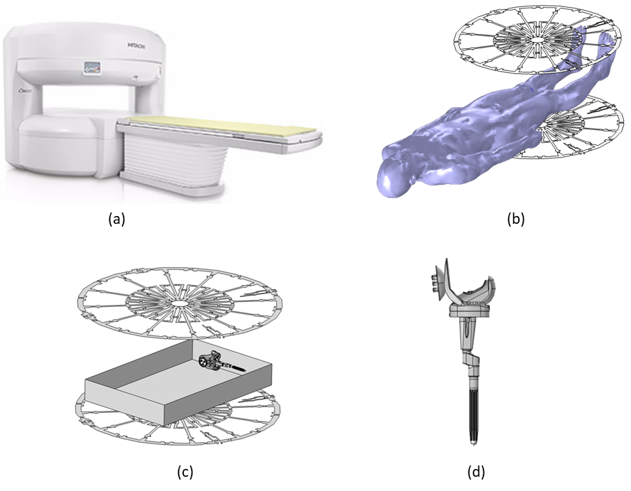
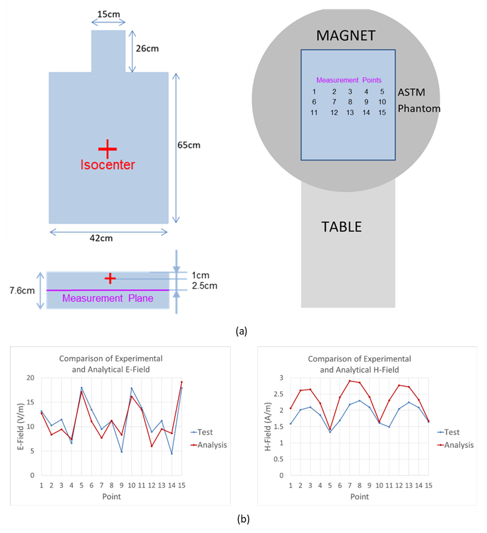
COMSOL Multiphysics® was used to build a computational model for the 1.2T Hitachi Oasis open bore MRI system which solves the sequentially coupled electromagnetic and transient heat transfer problem. The model was built using the geometric details of the RF coil provided by Hitachi. Figure 1 shows an image of the Oasis MRI system, the modeled RF body coil with the Duke human model, a knee implant in an ASTM phantom, and the detailed CAD model of a knee implant.Validation of the computational model included magnetic and electric field measurements in an ASTM F2182 phantom [1]. The phantom was filled with saline (electrical conductivity of 0.27 S/m) to a depth of 7.6 cm and landmarked along the mid-length of the phantom. Measurements were conducted at 12 different locations on the plane 3.5 cm below the surface (2.5 cm below the isocenter) as shown in Figure 2 (a). Input voltages for the simulation were tuned to generate a similar level of electric field to that of the experiment. RF-induced heating simulations and experimental measurements of titanium calibration rods, a nitinol SFA stent, and a knee implant at various locations in a gel phantom were conducted. The phantom was filled with a gelled saline prepared according to ASTM F2182 (electrical conductivity of 0.47 ± 10% S/m). The phantom was filled with gel to a depth of 9 cm and centered on the patient table of the MRI system and landmarked along the mid-length of the phantom. Temperature measurements were recorded using a fiber optic probe system. The input voltages for the simulation were tuned to induce a whole phantom SAR of 2 W/Kg. The sequence protocol for the Oasis was adjusted to induce the same temperature rise on a calibration rod as that of the simulation under the test configuration. The results were compared with those obtained from the simulation using an existing computational model of a 1.5T Siemens Avanto closed bore MRI system [2].
Results and Discussion
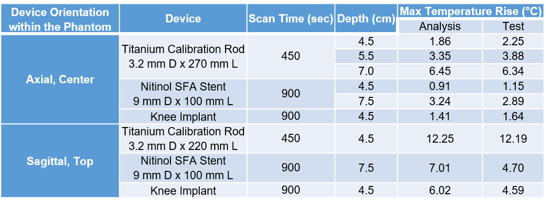
Experimental and simulation results for electric and magnetic fields in an ASTM phantom in the open bore Oasis agreed well both qualitatively and quantitatively showing a similar trend at the measurement locations as shown in Figure 2 (b). Since the input voltages for the simulation were tuned to induce a similar level of electric field to that of the measurement, the electric field showed better agreement than the magnetic field.RF heating experiments and simulations of calibration rods, a stent, and a knee implant within an ASTM Phantom in Oasis were conducted. As shown in Table 1, temperature rise values under different test configurations agreed well considering the level of simplification of the computational model compared to the actual MRI system as described above.
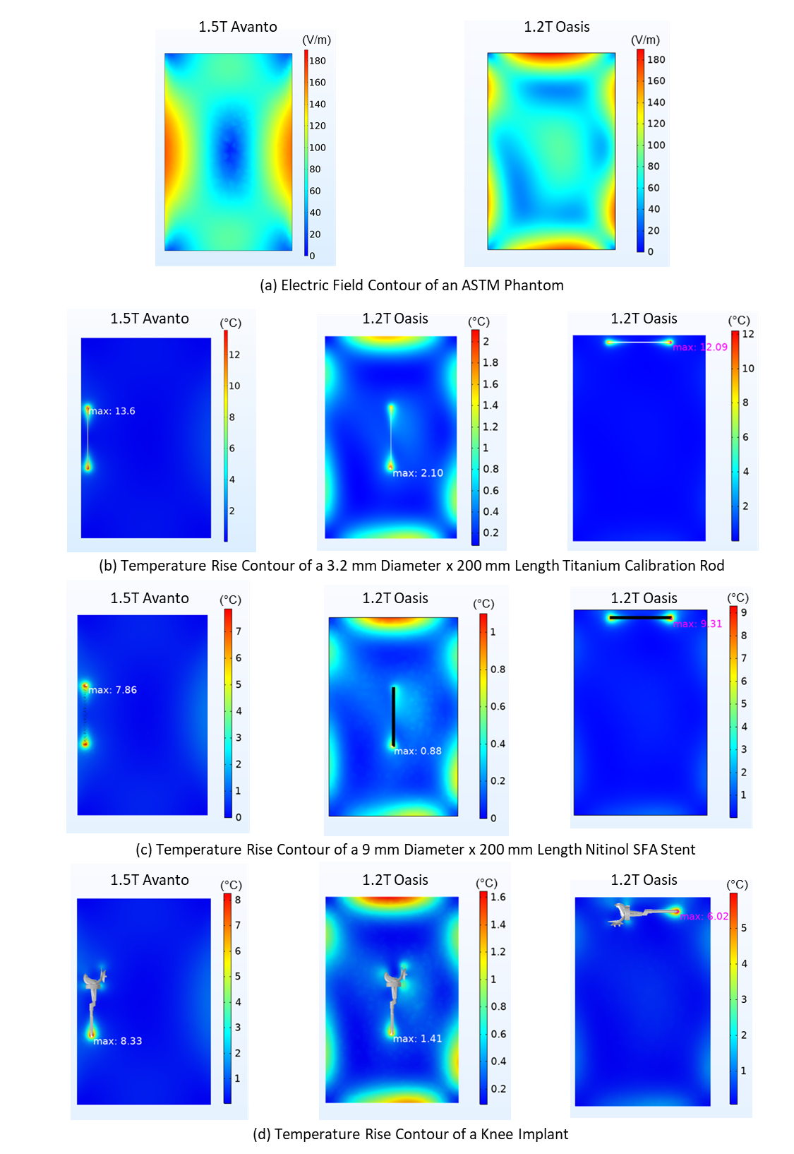
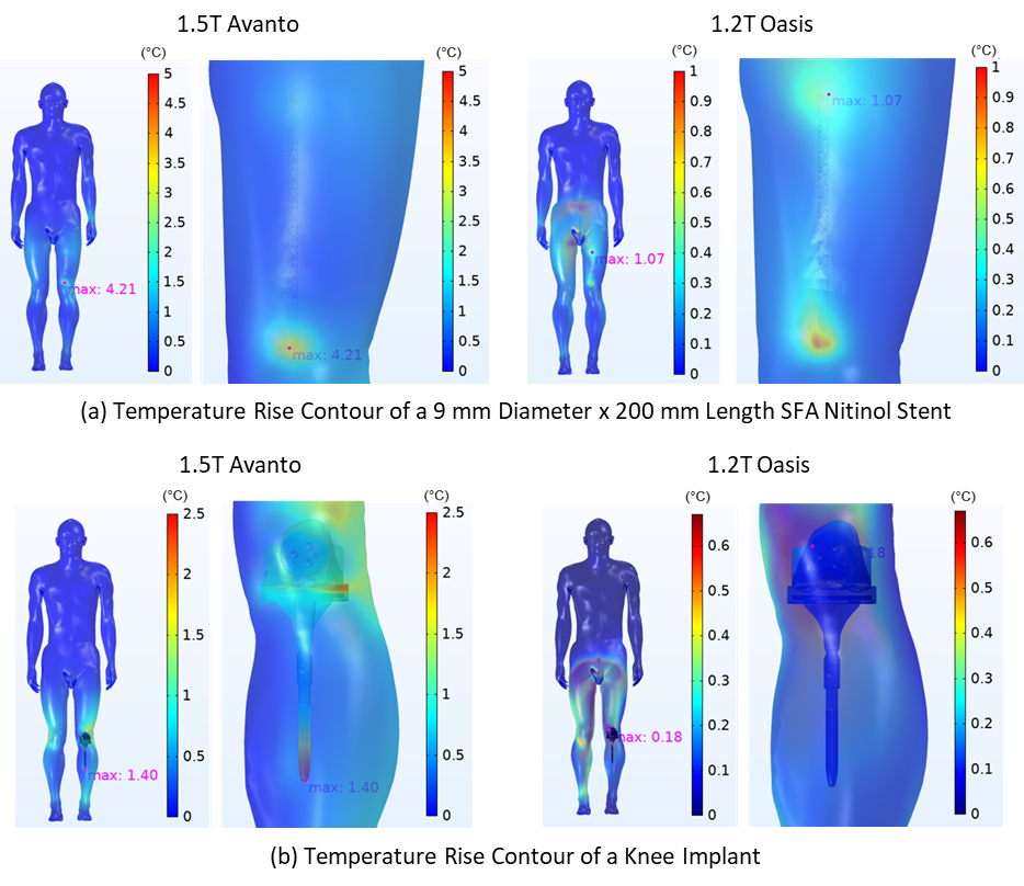
A comparison of Oasis and Avanto was performed with an analysis of the electric field in a phantom and RF heating simulations of a calibration rod, a stent, and a knee implant within the phantom (Figure 3) and the stent and knee implant within Duke (Figure 4). Both systems induced a similar level of electric field strength in an ASTM phantom, when set to provide a whole phantom SAR of 2 W/kg, but the electric field distributions were different. When the devices were placed in the region with high electric field, left-hand side for Avanto and top side for Oasis, they had a similar level of temperature rise. The Avanto generated significantly higher temperature rise in the stent and knee implant within Duke when compared to the Oasis open bore, due to the orientation of the devices within Duke relative to the high electric field. The devices were oriented parallel to the high electric field in the Avanto while they were perpendicular in the Oasis open bore.
Conclusions
Development and validation of an open bore computational model were demonstrated in this study. This computational model will aid in the understanding of RF-induced heating of medical devices in open bore MRI. The results show good agreement between the experiment and computational model. The 1.2T Hitachi Oasis open bore and a 1.5T Siemens Avanto closed bore systems induced a similar maximum level of electric field strength in a phantom, when the RF coils were powered to provide a whole phantom SAR of 2 W/kg. However, the electric field distributions are very different between the closed bore and open bore MRI systems. Future experiments and simulations will be used to quantify RF-induced heating in open bore MRI for the purpose of MRI labeling of medical devices according to ASTM F2503 [3].Acknowledgements
The authors would like to thank Hitachi Healthcare America (Twinsburg, OH) for financial support of this project, for providing the RF coil model details, providing access to and running the 1.2T Hitachi Oasis open bore MRI system, and providing E-field and H-field measurements performed with FDA. The authors are grateful for Exactech (Gainesville, FL) providing the knee implant and CAD model used in this study, and Cook Medical (Bloomington, IN) providing the stent used in this study. The authors thank AltaSim Technologies (Columbus, OH) for their help with the development and validation of the RF coil models in COMSOL Multiphysics®.References
[1] ASTM F2182-19e2, Standard Test Method for Measurement of Radio Frequency Induced Heating On or Near Passive Implants During Magnetic Resonance Imaging, ASTM International, 2019.
[2] A. Leewood, B. Hess, M. S. Huser, S. H. Gopal, G. G. Mendoza, M. I. Iacono, W. Kainz, S. S. Rajan and L. M. Angelone, "Simplified computational models of medical devices for accurate RF heating simulations with significantly reduced computational cost," in Proceedings from ISMRM 23rd Annual Meeting, Toronto, ON, Canada, May 2015.
[3] ASTM F2503-20, Standard Practice for Marking Medical Devices and Other Items for Safety in the Magnetic Resonance Environment, ASTM International, 2020.
Figures