2191
Correction of Image Distortions Arising from RF Encoding with Nonlinear Fields1Center for Magnetic Resonance Research and Department of Biomedical Engineering, University of Minnesota, Minneapolis, MN, United States, 2Center for Magnetic Resonance Research and Department of Radiology, University of Minnesota, Minneapolis, MN, United States
Synopsis
In this work, we investigate whether an established method to correct distortions in conventional MRI can be repurposed to correct distortions arising from the nonlinearity of B1 gradients when performing RF-encoded MRI at low field, where SAR constraints are reduced. Although several methods are capable of correcting image distortions arising from nonlinear B0 gradients and/or large B0 inhomogeneity, here we chose to adapt the method of Weis et al. Through theory and simulations, we demonstrate the ability to correct image distortions arising from nonlinear B1 gradients in RF-encoded MRI.
Purpose
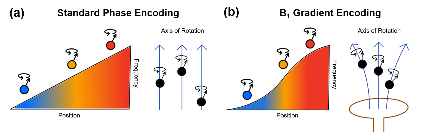
If it were possible to eliminate the need for B0 gradients in MRI, the benefits would include cost-savings, increased bore space, and silent scanning1. At low field where SAR constraints are reduced, spatial encoding with RF field gradients instead of B0 gradients is a viable option1-7. However, one challenge is creating efficient RF coils capable of producing linear B1 gradients for Fourier imaging (Fig. 1). To produce sufficient B1 amplitudes over the object required for spatial encoding, surface coils are often used as RF transmitters in RF-encoding methods8. To minimize image distortions, the object is usually confined to the approximately linear region of the surface coil’s B1 profile, which is less than ideal1. In this work, we investigate whether an established method to correct distortions in conventional MRI can be repurposed to correct distortions arising from the nonlinearity of B1 gradients when performing RF-encoded MRI. Although several9 methods are capable of correcting image distortions arising from nonlinear B0 gradients and/or large B0 inhomogeneity, here we chose to adapt the method of Weis et al10. Through theory and simulations, we demonstrate the ability to correct image distortions arising from nonlinear B1 gradients in RF-encoded MRI.Methods
The signal (\(s\left(n\right)\)) from the basic RF gradient encoding sequence considered here, namely rotating frame zeugmatography (RFZ), can be described similarly to a 1D phase encoding experiment in standard MRI, with the difference of substituting the B1 gradient (\(B_{1\ grad}\left(x\right)\)) for the conventional gradient,\[s\left(n\right)=\int{M_{xy}\left(x\right)exp\left(-i\left(xk_{lin}\left(n\right)+\gamma\Delta B_{1\ grad}\left(x\right)n\tau\right)\right)dx}\text{,}\qquad\textbf{(1)}\]
where we have also taken the additional step of decomposing \(B_{1\ grad}\left(x\right)\) into its linear and nonlinear components: \(B_{1\ grad}\left(x\right)=g_xx+\Delta B_{1\ grad}\left(x\right)\), for reasons that will subsequently be apparent. Here, \(n\in\left[-{\frac{N}{2}\ ,\ }{\frac{N}{2}}-1\right]\) is the index of the phase-encoding step (\(N=256\)), \(\tau\) is the incremental pulse width, and \(k_{lin}\left(n\right)=\gamma\ g_xn\tau\) is the k-space coordinate. Note that though the conventional MRI phase encoding experiment is insensitive to B0 inhomogeneity, it too is sensitive to gradient nonlinearity. Now we define the distorted coordinate system: \(x^\prime=x\ +\ \Delta B_{1\ grad}\left(x\right)/g_x\); calculate the Jacobian, \(J\left(x\right)=1+\frac{\partial\Delta B_{1grad}\left(x\right)}{\partial x}/g_x\), and using these, minor rearrangement of Eq. 1 yields,
\[s\left(n\right)=\int{M_{xy}\left(x^\prime\right)exp\left(-ik_{lin}\left(n\right)x^\prime\right)J^{-1}\left(x^\prime\right)}dx^\prime\text{,}\qquad\textbf{(2)}\]
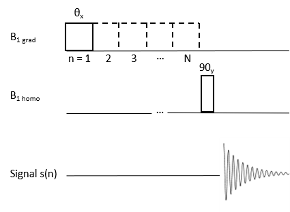
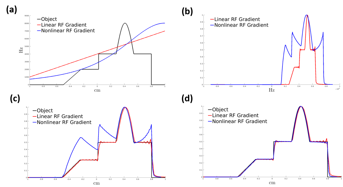
where \(J^{-1}\left(x^\prime\right)\) is the reciprocal of the Jacobian. Application of IFT to Eq. 2, yields the distorted reconstruction: \(I_{dist}\left(x^\prime\right)=M_{xy}\left(x^\prime\right)J^{-1}\left(x^\prime\right)\). Analyzing this equation, we see that the distortion caused by RF gradient nonlinearity comprises two components: a) a geometric distortion arising from the distorted coordinate (\(x^\prime\)), and b) an intensity distortion described by the reciprocal of the Jacobian (\(J^{-1}(x\prime))\)). Our adapted distortion correction algorithm thus first corrects the geometric distortion via usage of interpolation and then subsequently performs intensity correction by scaling with the Jacobian. To demonstrate this correction method, we modeled a 1D numerical phantom and simulated RFZ using both a linear field and nonlinear field (Fig. 3a). The nonlinear field describes that of a surface coil; it was calculated using the Biot-Savart law. The linear field was designed to place the object in roughly the same range of frequencies as the nonlinear field for comparison purposes. Signal measurements on the numerical phantom were simulated using the pulse sequence depicted in (Fig. 2). Both 1D images (1x256) were then reconstructed via FFT. Subsequently, the correction algorithm was applied. Simulation parameters were: \(\tau=55.6\mu s\), \(N=256\) the simulated scan is \(.917s\).
Results/Discussion
Fig. 3b shows the reconstructed images. RF gradient imaging with linear fields yielded no distortions, whereas imaging with nonlinear fields did. Distortions increased in severity in regions with increasing nonlinearity. These distortions can be corrected according to our method (Fig. 3c, d). Like in the case of standard MRI, distortion correction cannot account for the variable spatial resolution and signal-to-noise ratio that arises when encoding spatial information with nonlinear gradients.Conclusion
In this study, we demonstrate that, by using a map of the RF gradient, it is feasible to correct image distortions that arise from RF gradient nonlinearity. Simulated reconstructions showed that distortion severity increased in regions with increasing nonlinearity, but that these can be corrected by our method. This approach addresses one of the barriers to the practical use of a transmitted B1 gradient, like that produced by a surface coil, for spatial encoding in MRI.Acknowledgements
Schott Family Foundation, the Minnesota Lions, NIH grants P41 EB027061 and U01 EB025153.References
1. Canet, D. Radiofrequency field gradient experiments. Progress in Nuclear Magnetic Resonance Spectroscopy 30, 101–135 (1997).
2. Hoult, D. I. Rotating frame zeugmatography. Journal of Magnetic Resonance (1969) 33, 183–197 (1979).
3. Maffei, P. et al. NMR Microscopy by Radiofrequency Field Gradients. Journal of Magnetic Resonance, Series A 107, 40–49 (1994).
4. Sharp, J. C. & King, S. B. MRI using radiofrequency magnetic field phase gradients. Magnetic Resonance in Medicine 63, 151–161 (2010).
5. Wan, Yuqing et al. Nonlinear RF spatial encoding with multiple transmit coils based on Bloch-Siegert shift [abstract]. In: Proceedings of the 24th Annual Meeting of the International Society for Magnetic Resonance in Medicine; 2016 May 7-13; Singapore.
6. Katscher, U., Lisinski, J. & Börnert, P. RF encoding using a multielement parallel transmit system. Magnetic Resonance in Medicine 63, 1463–1470 (2010). Canot
7. Casanova, F., Robert, H., Perlo, J. & Pusiol, D. Echo-planar rotating-frame imaging. Journal of Magnetic Resonance 162, 396–401 (2003).
8. Garwood, M. Localized MRS employing radiofrequency field (B1) gradients. eMagRes 5, 1015–1026 (2016).
9. Mullen, M. & Garwood, M. Contemporary approaches to high-field magnetic resonance imaging with large field inhomogeneity. Progress in Nuclear Magnetic Resonance Spectroscopy 120–121, 95–108 (2020).
10. Weis, J. & Budinský, L. Simulation of the influence of magnetic field inhomogeneity and distortion correction in MR imaging. Magnetic Resonance Imaging 8, 483–489 (1990).
Figures