2155
Reusable 3D printed enclosure with integrated cutting guides for the alignment of ex-vivo MRI with ex-vivo gross brain photographs1Bioengineering, University of Pittsburgh, Pittsburgh, PA, United States, 2Pathology, UPMC, Pittsburgh, PA, United States, 3Alzheimer's Disease Research Center, University of Pittsburgh, Pittsburgh, PA, United States, 4Pathology, University of Pittsburgh, Pittsburgh, PA, United States, 5Neurology, University of Pittsburgh, Pittsburgh, PA, United States, 6Psychiatry, University of Pittsburgh, Pittsburgh, PA, United States, 7Radiology, University of Pittsburgh, Pittsburgh, PA, United States
Synopsis
In this project, we implemented a novel approach to align ex-vivo MRI brain images and gross neuropathology photographs with minimal image processing. The approach included the design and implementation of a reusable 3D printed enclosure with integrated cutting guides . Our results show a good alignment between ex-vivo high field MRI and gross brain image photographs.
Introduction
Ex-vivo brain MRI is a necessary research tool that enables high-resolution visualization of neuroanatomy [1], validation of quantitative MRI results [2] and discovery of new imaging biomarkers [3]. Ex-vivo brain MRI is not affected by motion artifacts caused by patients’ movement and physiology. Ex-vivo brain MRI can be scanned for long hours to increase SNR and resolution. Moreover, an accurate colocalization between a histology sample and an ex-vivo finding can have a great translational utility to further understand neuroradiological findings. Software only approaches [4]to register ex-vivo MRI and histology can introduce computational image artifacts. Instead, several groups have designed 3D cutting individual guides from MRI images to enable the alignment with histology with minimal image processing [5][6][7]. printing individual containers, however, can be cost-prohibitive for large studies. The long-term goal of this work is to achieve accurate histology to premortem MRI registration. The first step towards this goal is to achieve a good alignment between ex-vivo and gross pathology brain slabs. We present a reusable 3D printed enclosure that enables the alignment of gross images with ex-vivo with minimal image processing.Methods
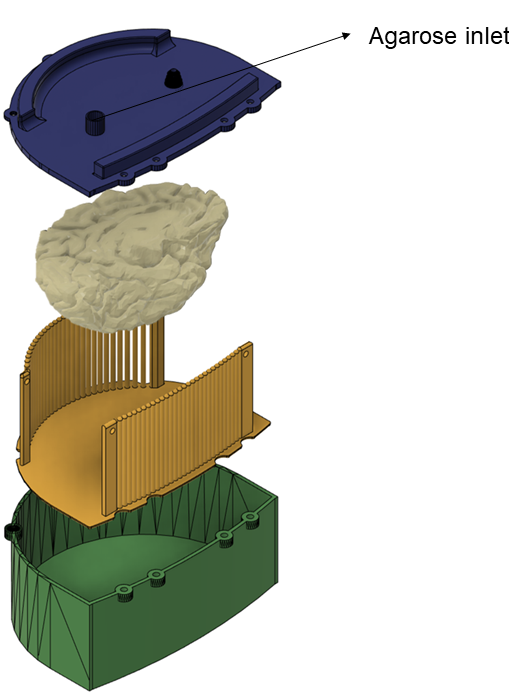
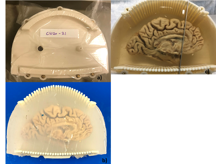
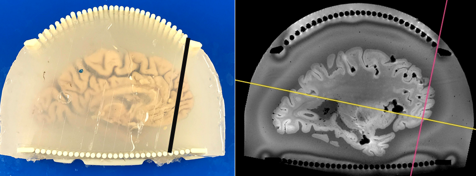
We have designed a 3D printed enclosure contains the left hemisphere brains. The enclosure conforms to the brain shape (Fig1- green). Also, we have designed a cutting guide (Fig1- yellow) that goes inside the enclosure. On the day of the scanning, the 3D printed cutting guide is first inserted in the enclosure, then ex-vivo brains, which were fixed in PFA 4% for 3 weeks, are inserted in the cutting guides. The left brains are massaged to reduce air bubble content and agarose embedding media (1.5% agarose, 30 % sugar) is poured inside the container until the brain is fully immersed. We close the enclosure with the lid (Fig1- blue) and we continue filling the enclosure with agarose through the inlet in the lid (Fig-1- black arrow). The enclosure is set aside for a few hours for the embedding media to solidify. Then, we insert the enclosure inside the head coil for the MRI scans. The ex-vivo MRI scans were acquired using a 7 Tesla MRI scanner (Siemens MAGNETOM, Germany) with a Tic-Tac-Toe (TTT) head coil composed of a 16-channel transmit array and a 32-channel receive insert, for optimal receiving performance. The TTT transmit array has been shown to produce a homogenous spin excitation at 7T frequencies [8]. We have used the GRE pulse sequence with the following parameters: TR = 40ms, TE1 = 8 ms, TE2 = 15 ms, TE3 = 21 ms, number of slices = 512 and voxel size = 0.37 x0.37x0.37 mm3 After the MRI sessions, the pathologist reviews the MRI images to plan the cuts. The cutting guides are then removed with the left brain and the embedding media from the enclosure (Fig2-b). Before cutting the brain into slabs, the pathologist aligns the knife between two columns (Fig2-c), records the knife alignment for each slab, and starts cutting the brain into slabs, while taking a photograph for each slab. After the brain cutting, the pictures of the knife alignments are then used to reorient the ex-vivo brain coronal slices into the same orientation of the photographs of the slabs (Fig 3).Results
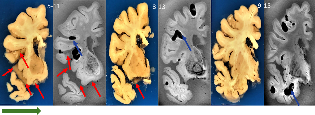
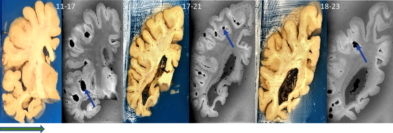
We have achieved a good alignment between gross photographs and ex-vivo brain MRI images (Figs 4 and 5). The image slices and photograph slabs sample the brain in the coronal direction from the anterior towards the posterior of the brain (prefrontal lobe towards occipital lobe). Some ex-vivo MRI images contained susceptibility artifacts due to the presence of air bubbles.Discussion and Conclusion
In this project we have used a multistep procedure to allow for a good alignment between ex-vivo brain MRI. The 3D enclosure conforms to the brain shape and allows placement of the ex-vivo brain in a very similar position to premortem imaging (supine). The cutting guide restricts the knife movements during the brain cutting and guides the knife. Also, the cutting guide columns do not have an MRI signal; therefore, they appear as void disks in the MRI. We can match the columns in MRI images to the exact columns in the photograph, thus the location of the knife during the actual brain cutting can be replicated during multiple planar reconstruction. Thus, the resultant ex-vivo reconstructed images have a very good alignment with the photographs of the slabs. The agarose embedding media protects the brain from deformation and motion during MRI scanning and brain cutting thus eliminating the need for further image processing. There are several limitations to our approach: the air bubbles cause susceptibility artifacts which are additionally bloomed in the GRE sequences. Air bubbles can be reduced by removing the leptomeninges, by controlling the temperature of the liquid agarose, and by using pulse sequences with less susceptibility artefacts. The cutting guide columns are printed in ABS 30 and last around 10 brain sessions, however we are exploring using more durable 3D printed materials such as polycarbonate.Acknowledgements
This work was supported by the National Institutes of Health under award numbers: R01MH111265, R01AG063525, T32MH119168.
This research was also supported in part by the University of Pittsburgh Center for Research Computing through the resources provided.
References
[1] B. L. Edlow et al., “7 Tesla MRI of the ex vivo human brain at 100 micron resolution,” Sci. data, vol. 6, no. 1, p. 244, 2019.
[2] C. Langkammer et al., “Quantitative susceptibility mapping (QSM) as a means to measure brain iron? A post mortem validation study,” Neuroimage, vol. 62, no. 3, pp. 1593–1599, Sep. 2012.
[3] A. D. Roseborough et al., “NeuroImage : Clinical Post-mortem 7 Tesla MRI detection of white matter hyperintensities : A multidisciplinary voxel-wise comparison of imaging and histological correlates,” NeuroImage Clin., vol. 27, no. January, p. 102340, 2020.
[4] M. Singh et al., “Co-registration of in vivo human MRI brain images to postmortem histological microscopic images,” Int. J. Imaging Syst. Technol., 2008.
[5] M. Absinta et al., “Postmortem Magnetic Resonance Imaging to Guide the Pathologic Cut,” J. Neuropathol. Exp. Neurol., vol. 73, no. 8, pp. 780–788, Aug. 2014.
[6] T. A. Steve et al., “Development of a histologically validated segmentation protocol for the hippocampal body,” Neuroimage, 2017.
[7] R. de Flores et al., “Characterization of hippocampal subfields using ex vivo MRI and histology data: Lessons for in vivo segmentation,” Hippocampus, 2020.
[8] T. Santini et al., “In-vivo and numerical analysis of the eigenmodes produced by a multi-level Tic-Tac-Toe head transmit array for 7 Tesla MRI,” PLoS One, vol. 13, no. 11, p. e0206127, Nov. 2018.
Figures