2095
A small-vessel MRI phantom for quantitative analysis of diffusion-weighted images: a validation study with numerical computation1Department of Medical Physics, Tohoku University, Graduate school of medicine, Sendai, Japan, 2Department of Advanced MRI Collaboration Research, Tohoku University, Graduate school of medicine, Sendai, Japan, 3Department of Radiology, Tohoku University hospital, Sendai, Japan, 4Institute of Fluid Science, Tohoku University, Sendai, Japan
Synopsis
We designed a 3-dimensional unicursal channel phantom to simulate small vessels and obtained diffusion-weighted images with varying infusion rate of water. The signal intensities were compared with theoretical data by numerical computation. Our model will allow for understanding the behavior of IVIM images under various flow conditions and evaluating performance of MRI platforms.
Introduction
Diffusion-weighted magnetic resonance imaging (DW-MRI) allows for the quantification of not only the random motion of self-diffusing water molecules but also the perfusion of the small and capillary vessels. Limited studies have been reported regarding the validation of quantitative perfusion imaging such as intravoxel incoherent motion (IVIM) imaging with phantom models. Ahn et al. simulated a capillary-network in random directions using balls made by winding a long flexible tube with 1-mm diameter1. Cho et al. used a cellulose sponge for the simulation2. Schneider et al. made the capillary network phantom by melt-spun sacrificial sugar fibers embedded in a synthetic resin3. The aim of this study was to develop a polydimethylsiloxane (PDMS)-based microfluidic phantom model simulating flow in small vessels and validate the quantitative measurement by IVIM with numerical computation.Materials and methods
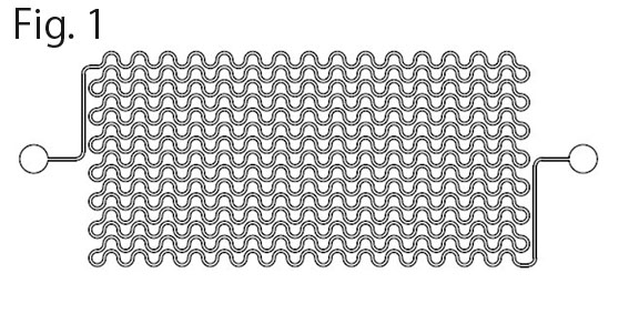
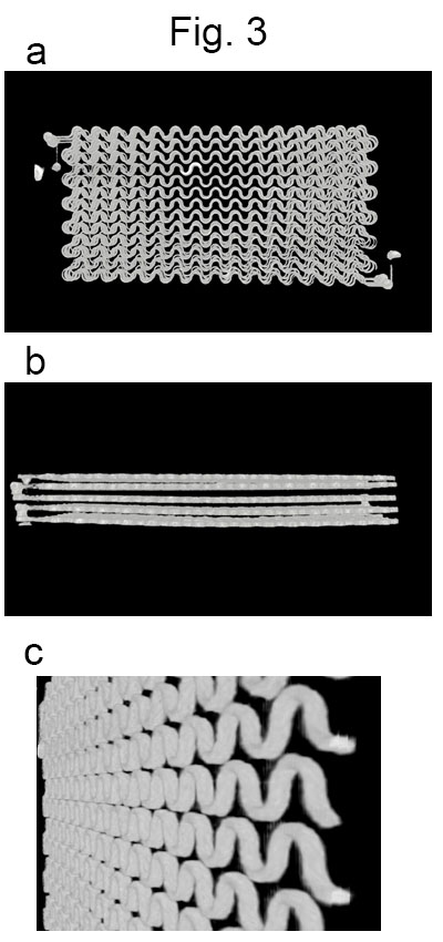
Microfluidic small-vessel phantom: A unicursal curved channel was designed (Fig. 1). The microfluidic phantom was fabricated from PDMS by means of photolithography and soft lithography4. The channel had 200 µm in width and 400 µm in depth. The phantom consisted of 5 layers of PDMS with the channel; the channels of adjacent layers were connected at the corners so that infused water unicursally flows from the inlet in the top layer to the outlet in the bottom layer (Fig. 2). Each layer had 0.5-mm thickness. Micro CT images of the phantom revealed accuracy and uniformity of the channel with errors of < 1% in width and <8% in depth (Fig. 3).MRI acquisition and image analysis: A clinical 3-Tesla MRI system (Ingenia CX, Philips, Best) with a dStream Head Spine coil was used. Acquisition parameters of DW-MRI were as follows: motion probing gradient (MPG) in orthogonal three directions, b = 0, 50 s/mm2, TR/TE, 3000/37 ms, the number of slice, 1, slice thickness, 5mm, field of volume, 320 mm, acquisition matrix: 64 x 62. The channel of the phantom was filled with tap water before the acquisition. During acquisition, tap water was infused at the rate of 0 – 0.7ml/hour (0.1 ml/hour increment) by MRI IV Infusion pump (Inradimed, Winter Springs, FL). Region of interests (ROIs) were placed on the acquired images to measure the signal intensities.
Results
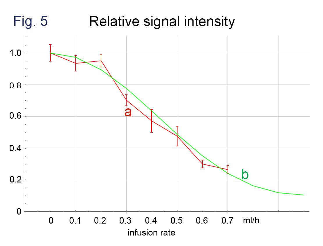
Significant decreases in signal intensity were observed along with the increases of infusion rate on b = 50 s/mm2 images where MRGs were applied parallel to the channel layer (Fig. 4). A little decrease in signal intensity was also observed on b = 0 s/mm2 images where the infusion rates were large. The observed signal intensities agreed with the results of computer simulation (Fig. 5).Discussion
The strictly designed 3-dimensional flow channel in the PMDS phantom allowed for simulating a small vascular network. Based on the proposed 3-dimensional structure, it is possible to evaluate signal intensity and compare it with theoretical values from MPG of pulse sequence. The observed signal intensity in this study was in agreement with numerical simulation following the MPG settings. However, we also observed small amount of signal decay along with the increase of flow rate even in the b = 0 s/mm2 images, indicating a positive b-value in the nominal zero-b sequence as expected. Further application of the phantom model will include understanding and interpretation of IVIM images acquired by various MRI platforms as well as evaluation of their performances.Conclusion
We designed a 3-dimensional unicursal channel phantom to simulate small vessels and obtained diffusion-weighted images with varying infusion rate of water. The signal intensities were compared with the theoretical values by numerical computation. Our model will allow for understanding the behavior of IVIM images under various flow conditions and evaluating performance of MRI platforms.Acknowledgements
No acknowledgement found.References
1. Ahn CB, Lee SY, Nalcioglu O, Cho ZH. The effects of random directional distributed flow in nuclear magnetic resonance imaging. Med Phys. 1987;14(1):43-48. doi:10.1118/1.596093
2. Cho GY, Kim S, Jensen JH, Storey P, Sodickson DK, Sigmund EE. A versatile flow phantom for intravoxel incoherent motion MRI. Magn Reson Med. 2012;67(6):1710-1720. doi:10.1002/mrm.23193
3. Schneider MJ, Gaass T, Ricke J, Dinkel J, Dietrich O. Assessment of intravoxel incoherent motion MRI with an artificial capillary network: analysis of biexponential and phase-distribution models. Magn Reson Med. 2019;82(4):1373-1384. doi:10.1002/mrm.27816
4. Koens R, Tabata Y, Serrano JC, et al. Microfluidic platform for three-dimensional cell culture under spatiotemporal heterogeneity of oxygen tension. APL Bioengineering. 2020;4(1):016106. doi:10.1063/1.5127069
Figures
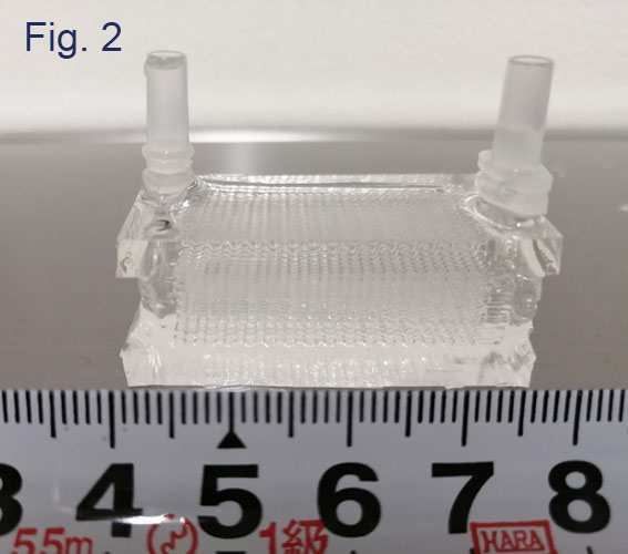
Images obtained by a micro CT unit (SKYSCAN1176, Bruker)
a. A front view. b. A side view. c. A tilted view of one layer.
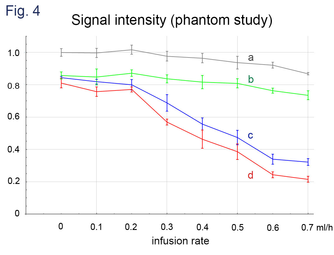
DWI signal intensities obtained with infusion rate of 0-0.7 ml/h. The intensities are normalized to that of b = 0 and the infusion rate = 0.
a: b = 0.
b: b = 50 s/mm2, MPG of perpendicular to the imaging plane that is parallel to the phantom flow channel layer.
c: b = 50 s/mm2, MPG of the readout direction (parallel to the phantom flow channel layer and parallel to the flow channel).
d: b = 50 s/mm2, MPG of the phase encoding direction (parallel to the phantom flow channel layer and perpendicular to the flow channel).