2009
Phase Correction in IDEAL-type Rapid Spectroscopic Imaging1INRAE, AgroResonance, UR QuaPA, F-63122, Saint-Gènes-Champanelle, France, 2University of Lyon, INSA‐Lyon, Université Claude Bernard Lyon 1, UJM Saint-Etienne, CNRS, Inserm, CREATIS UMR 5220, U1206, F‐69621, Lyon, France
Synopsis
In IDEAL-type sequences, spectral selective pulses are done with an excitation frequency fe dependent on the slice position, and the acquisition is applied with a reception frequency fr. For a proper spectral study, the phase observed during the different evolution times of each shot (TE) has to be dependent only on the CS. A phase coherent fe-fr switch is applied throughout the pulse sequence. However, depending on the frequency commutation position, phase errors are accumulated, disturbing the CS study. This presentation elucidates the impact of the commutation's position and how to correct to resulting phase errors.
Introduction
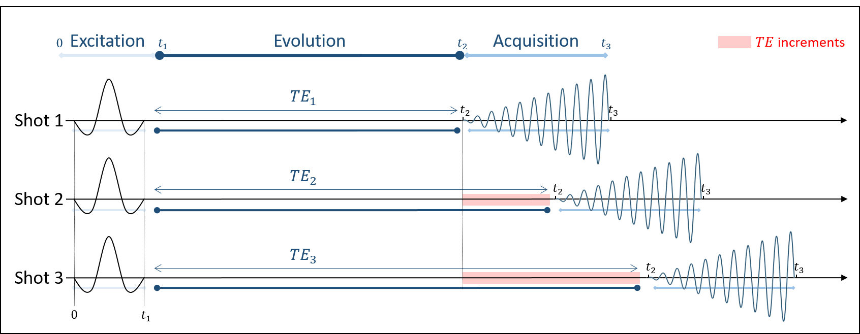
In order to reduce acquisition time and increase spectral bandwidth in MRSI, it is useful to acquire several experiments with slightly different echo timing, as in IDEAL-type sequences (multi-shot) [1] presented in Figure 1. Here, the chemical shift (CS) information is acquired in multi-shot, where the echo time (TE) is incremented once per shot to sample the signal nonlinearly. The excitation is done with a spectral selective pulse with an excitation frequency fe, and the acquisition is applied with a spiral-OUT trajectory with a reception frequency fr. A coherent switch between both frequencies has to be applied throughout the pulse sequence. For proper CS study, the phase acquired during TE, at t2, should only depend on the CS and not be prone to the influence of the pulse sequence. However, a spurious phase can be accumulated during the TE depending on the frequency commutation position leading to phase errors. This presentation aims to explain how the position of the frequency switch affects the spectral study and how to overcome the resulting phase errors.Theory
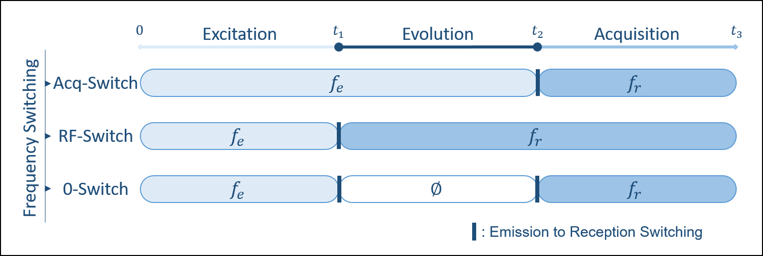
Firstly, during the excitation time, the slice selective gradient is applied, making the excitation frequency fe dependent on the slice position in the z-direction (fe ∝ z, fe=0 for a centred slice z=0 and fe≠0 for a shifted one). Secondly, the different echo times (TE) correspond to the evolution time where the CS's phase variation is studied through TE increment. Finally, during the acquisition time, fr can be non-nil under certain circumstances explained in the presentation. If the phase's evolution during the different TEs must depend only on the CS for each shot, it can also depend on either fe or fr depending on when the emission/reception switching is performed. We present the three possible frequency-switch cases (see Figure 2): i) Acq-Switch, fe-fr commutation at t2; ii) RF-Switch, fe-fr commutation at t1; and iii) double 0-Switch, fe-0 commutation at t1 and 0-fr commutation at t2. Using Acq-Switch or RF-Switch case leads to unwanted phase accumulation when fe or fr is non-nil, respectively. This spurious phase has to be eliminated from the acquired signal before spectroscopic image reconstruction. The double 0-Switch case leads to no phase accumulation, making the acquired signal free of sequence-dependent phase.Method
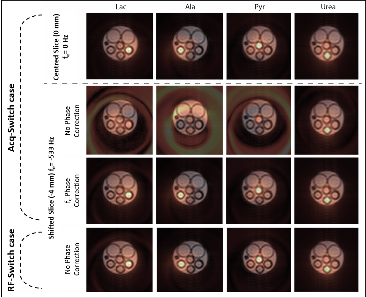
IDEAL SPIRAL pulse sequence was applied at 11.7 T on a phantom composed of four syringes filled with either [1-13C]Pyruvic acid, [1-13C]Lactate, [1-13C]Alanine, or [1-13C]Urea fixed in 10% gelatine. Seven shots were applied with an echo time increment of 0.86 ms, determined through NSA analysis [1]. The spectroscopic (CS) images were reconstructed with the least square estimation approach described in [1]. The pulse sequence was applied using the Acq-Switch case for a centred (0 mm, fe=0) and a shifted slice (-4 mm, fe=-533Hz), and the RF-Switch case for the shifted one. Using spiral-OUT trajectory leads to a nil fr.Results
In Figure 3, each row presents each metabolite's 13C image, superimposed on a 1H reference image of the phantom. Row 1 presents the acquired images using the Acq-Switch case for the centred slice. The metabolic images are well reconstructed and correspond to the reference image. Row 2 presents the images generated for the shifted slice, where phase errors occur and the CS information is lost. Row 3 shows the same acquired images but after fe phase correction. The metabolic images are, therefore, well reconstructed. Row 4 presents the images acquired using the RF-Switch case for a shifted slice. As fr=0, no unwanted phase was accumulated, and the metabolic images are successfully reconstructed without any phase correction.Conclusion
During the different evolution times (TE), unwanted phase shifts are likely to be accumulated due to non-nil excitation or reception frequency (fe or fr) for Acq- or RF-Switch case, respectively. These phase errors disrupt the CS information and lead to incorrect metabolic image reconstruction. Phase correction has to be applied by removing the spurious phase prone to the pulse sequence. The framework presented is general and it clarifies the different situations and possible solutions for phase errorsAcknowledgements
No acknowledgement found.References
1- Wiesinger F, Weidl E, Menzel MI et al. IDEAL SPIRAL CSI for Dynamic Metabolic MR Imaging of Hyperpolarized [1-13C]Pyruvate. Magn. Reson. Med. 2012;68(1):8-16.
Figures