1813
Three-Dimensional Sodium MRI Using A Rotation of Spiral Disc (RSD) Trajectory1Beckman Institute for Advanced Science and Technology, University of Illinois at Urbana-Champaign, Urbana, IL, United States, 2Electrical & Computer Engineering, University of Illinois at Urbana-Champaign, Urbana, IL, United States
Synopsis
Sodium MRI is challenging due to its low sensitivity and short T2 and hence a three-dimensional sequence with a spiral trajectory has been applied. The spiral trajectory was shortened in the TPI method by accelerating the span at the k-space origin using a radial start and then transiting into a spiral trajectory. This popular TPI method, however, requires a very high gradient slew rate when the 3D cone approaches the polar pole. This drawback has been resolved by rotating a two-dimensional disc filled with interleaved TPI trajectories. This method achieved the faster sweeping of TPI as well as a uniform gradient slew rate over the sphere sampling. We are reporting some artifacts in TPI-based scans not only in our study but also in other studies.
INTRODUCTION
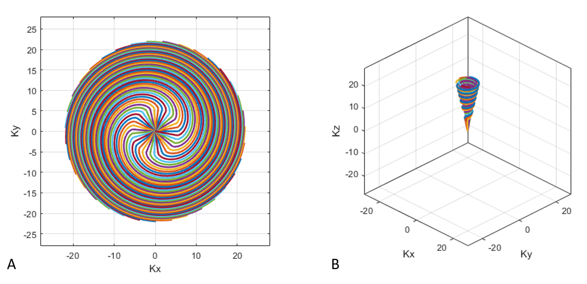
Sodium MRI is challenging due to its low sensitivity and short T2,1 and hence a three-dimensional sequence with a spiral trajectory2 has been applied. The spiral trajectory was shortened by accelerating the span at the K-space origin using a radial start and then transiting into a spiral trajectory. There are three schemes of this method: TWIRL3, WHIRL4, and Twisted Projection Imaging (TPI)5. Here, we are focusing on TPI due to its availability of a pulse sequence at our center. The three-dimension sampling of TPI was achieved by using cones that span from an equator to polar poles. The gradient slew rate becomes proportionally high with the cone’s polar angle shown in Fig. 1, which prevents the use of MRI system’s gradient capacity. Here, we changed the TPI trajectory to RSD trajectory that rotates a disc filled with two-dimensional TPI trajectories to maximize the use of the system’s gradient capacity.6METHODS
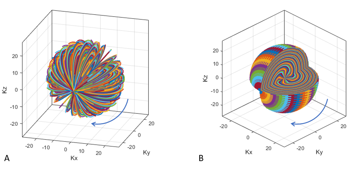
The disc of K-space was filled with interleaved TPI trajectories using Lu’s design7 as shown in Fig. 1. The disc was then rotated around x-axis to fill a 3D K-space sphere (Fig. 2). The gradient pulses were loaded into a sodium MRI sequence that was designed to read a stack of gradient pulses of arbitrary waveforms in an xml file format. The experiment was conducted on a phantom using Siemens 3T Prisma scanner with a custom-built quadrature sodium RF coil. An iterative algorithm was used for image reconstruction.8 The trajectory parameters were: radial fraction = 0.25, gradient amplitude = 4 mT/m, gradient slew rate = 150 T/m/s, matrix size = 44, and field-of-view = 28 cm, which resulted in 71 discs with 35 spiral interleaves in each disc. The scan parameters were: RF = rectangular pulse, TR = 100 ms, TE = 0.5 ms, and field-of-view = 280 mm. The object was bottles and tubes that were filled with sodium of various concentrations between 10 to 200 mM.RESULTS
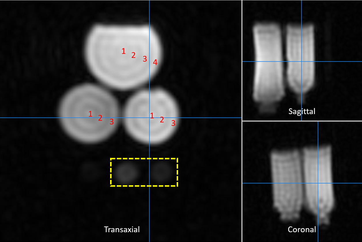
The RSD required 2845 shots in covering the K-space sphere compared to 1576 shots of TPI. Therefore, the RSD was less effective in covering the 3D K-space than TPI. However, the TPI sequence made a high pitch gradient noise when the polar angle approached polar poles due to a fast twisting of gradient pulses. On the other hand, the proposed RSD sequence maintained the same level of gradient noise as the disc rotated, which confirmed the avoidance of the increased slew rate of the TPI trajectory. The 3D image obtained using the RSD trajectory is shown in Fig. 3. Note the annular artifacts on bottles of large diameters and a dark spot at the center of smaller tube at the bottom.DISCUSSION
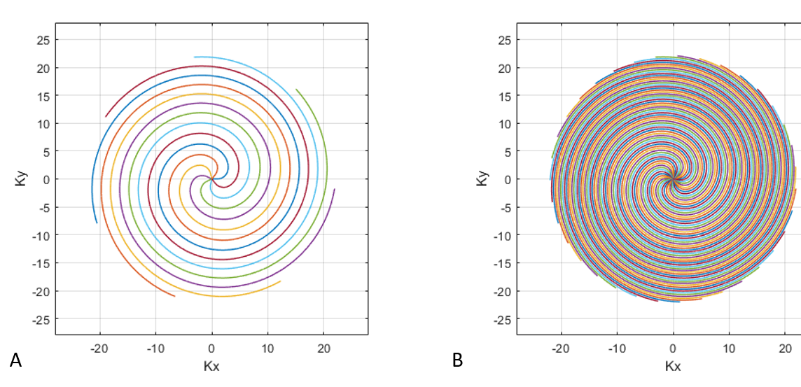
The number of rings of annular artifacts varied by the diameter of bottles. We suspected under-sampling effects and tested the effect of increased number of discs and interleaves on the annular artifacts. However, the annular artifacts persisted independent of the trajectory parameters. The dark spot was observed in most of sodium publications using the same TPI trajectory including Lu’s paper7. We are suspicious that the dark spot might be contributed from the same effect of the annular artifacts in this study. In the published papers, dark spots were not observed in the eyeballs, but this might be due to saturated sodium intensity of eyeballs. We also noticed that the sampling density is sparser at the transition point from radial to spiral trajectory. This can be improved by replacing the TPI scheme with TWIRP3 or WHIRP4 trajectories as demonstrated in Fig. 4, which is under evaluation.CONCLUSION
The gradient slew rate limitation in the TPI method has been removed using the proposed RSD method. The RSD method can be further expanded to other spiral trajectory methods such as TWIRL and WHIRL. The dark spots were observed not only in our studies but also in other studies with the TPI trajectory. We hope to explain this issue and provide a solution in a future study.Acknowledgements
A graduate student, Hsin-Yu Fang, is greatly appreciated in reporting the artifacts from her sodium invivo study and preparing sodium phantoms for this study.References
1. Hilal SK, Maudsley AA, Simon HE, Perman WH, Bonn J, Mawad ME et al. In vivo NMR imaging of tissue sodium in the intact cat before and after acute cerebral stroke. AJNR Am J Neuroradiol. 1983;4(3):245-9.
2. Ahn CB, Kim JH, Cho ZH. High-speed spiral-scan echo planar NMR imaging-I. IEEE Trans Med Imaging. 1986;5(1):2-7. doi:10.1109/TMI.1986.4307732.
3. Jackson JI, Nishimura DG, Macovski A. Twisting radial lines with application to robust magnetic resonance imaging of irregular flow. Magn Reson Med. 1992;25(1):128-39. doi:10.1002/mrm.1910250113.
4. Pipe JG. An optimized center-out k-space trajectory for multishot MRI: comparison with spiral and projection reconstruction. Magn Reson Med. 1999;42(4):714-20. doi:10.1002/(sici)1522-2594(199910)42:4<714::aid-mrm13>3.0.co;2-g.
5. Boada FE, Gillen JS, Shen GX, Chang SY, Thulborn KR. Fast three dimensional sodium imaging. Magn Reson Med. 1997;37(5):706-15. doi:10.1002/mrm.1910370512.
6. Castets CR, Lefrancois W, Wecker D, Ribot EJ, Trotier AJ, Thiaudiere E et al. Fast 3D ultrashort echo-time spiral projection imaging using golden-angle: A flexible protocol for in vivo mouse imaging at high magnetic field. Magn Reson Med. 2017;77(5):1831-40. doi:10.1002/mrm.26263.
7. Lu A, Atkinson IC, Claiborne TC, Damen FC, Thulborn KR. Quantitative sodium imaging with a flexible twisted projection pulse sequence. Magn Reson Med. 2010;63(6):1583-93. doi:10.1002/mrm.22381. 8. Sutton BP, Noll DC, Fessler JA. Fast, iterative image reconstruction for MRI in the presence of field inhomogeneities. IEEE Trans Med Imaging. 2003;22(2):178-88. doi:10.1109/tmi.2002.808360.
Figures