1613
Turbulences in a one bifurcation 4mm diameter phantom after inflating a balloon catheter: a 4D flow/cine phase invitro study at systemic pressure.1Radiology, Centre de recherche du Centre hospitalier de l’Université de Montréal, Montreal, QC, Canada, 2Radiology, Université de Montréal, Montréal, QC, Canada, 3Polytechnique Montréal, Montréal, QC, Canada
Synopsis
Turbulent flow undermines steering of magnetic microrobots across bifurcations using the MRI gradients. A partial inflated balloon can reproduce a blood flow controlling method in vivo, to increase the targeted success rate of embolization by microrobots. At 3T MRI, 4D flow reveals that vortices in front of the catheter were generated. These series of vortices are also confirmed through by ink injection and under videos capture. At 4 mm diameter, 4D flow and cine phase are reproducible for average velocity and net flow at 0.8mm2 in plane resolution. These in vitro results can be used to refine 4D flow models.
Introduction
Clinicians commonly use balloon catheters for angioplasty and blood flow control during a hemorrhage or shock as with the intra-aortic balloon pump[1]. A novel use for balloon catheters is to limit arterial flow to allow intravascular steering of ferromagnetic microspheres with MRI gradients, a concept called magnetic resonance navigation (MRN)[2,3,4]. Controlled pulsatile flow decreases the friction force between the particles and the vessel wall [5] and provides enough hydrodynamic drag for particle progression downstream. The presence of the balloon generates turbulence which may undermine safe steering of microspheres. Thus, 2D cine phase, 4D flow, manual measures and ink injection were used to investigate flow patterns in realistic phantoms mimicking MRN conditions in the hepatic arteries.Methods
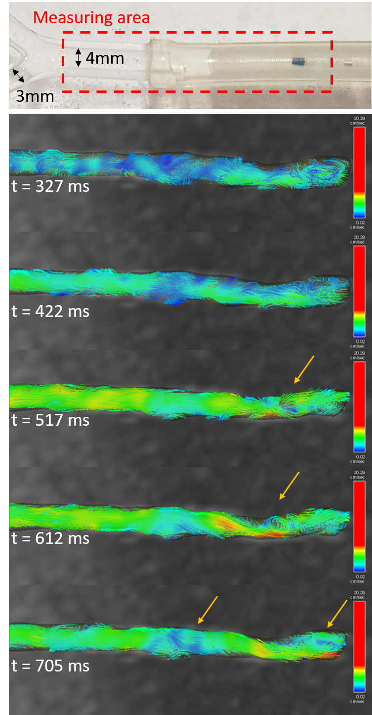
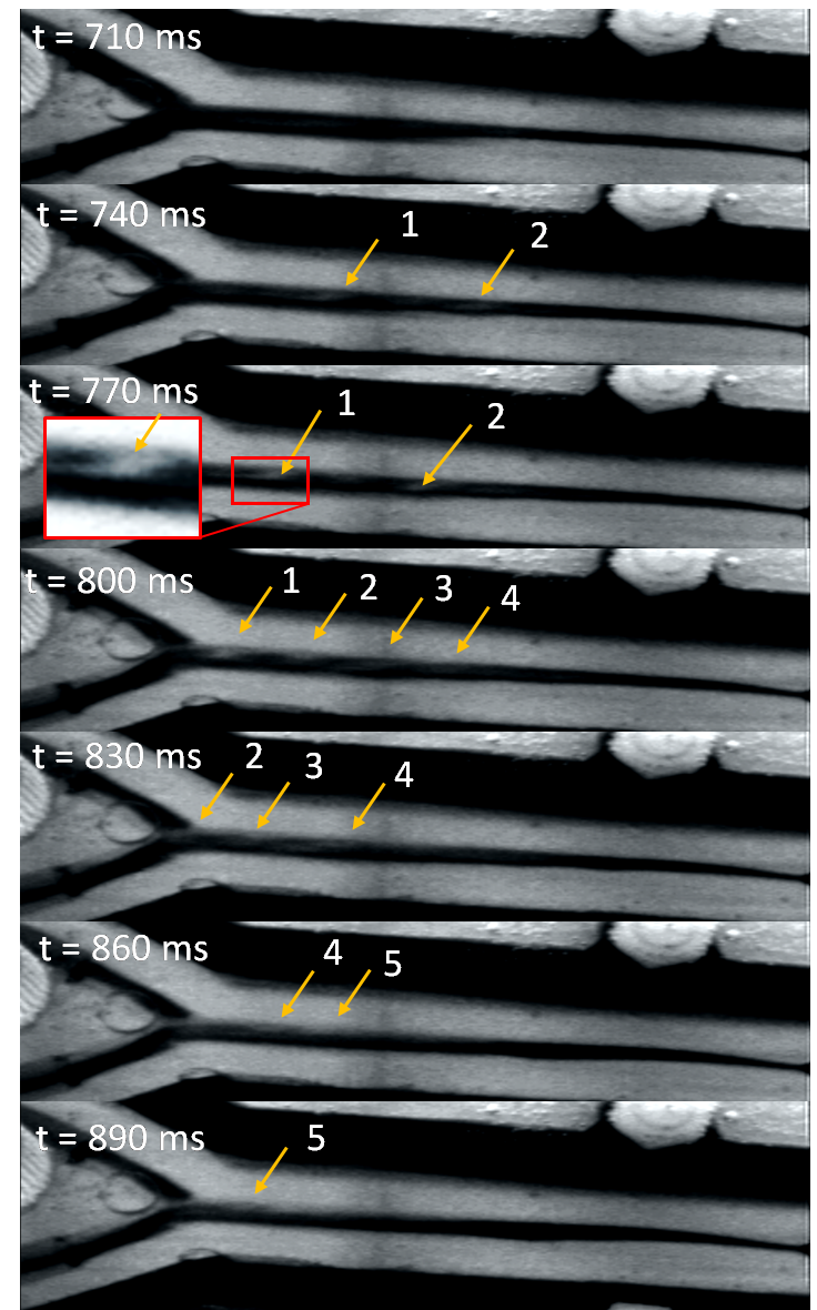
A one-bifurcation glass phantom (Internal diameter: 4mm main branch, 3 mm branches) was placed parallel to B0 in a 3T MRI scanner and perfused with 25°C water by a cardiac pump set at 60 beats per minute and 40 mL stroke volume. A second pump provided 0.2ml/s of water in the catheter. In total, the flow rate was 4ml/s in free flow and then decreased to 1.3 ml/s when a 5mm angioplasty balloon (0.9 ml water, 5Fr, Powerflex P3, Cordis) was partially inflated in the main branch lumen. The system was connected to a bypass with a pressure transducer, recording a pressure of 240/80 mmHg. From the pressure waveforms, a trigger signal was formed for the 4D Flow (Siemens WIP785B, Coronal, TR=94.72ms, TE=3.33ms, voxel=0.8x0.8x1.5mm3, slices=40, FOV=156x192, VENC=40cm/s, 10 phases cycle, mSENSE 3D factor=2, TA=4min) and the cine phase contrast sequences (TR=100.64ms, TE=3.61ms, voxel=0.4x0.4x3.7mm3, slice=1, FOV=200x200, VENC=40cm/s, TA=1min). The trigger position was set to 200 ms ahead of the lowest pressure point. Analysis was performed using Argus, WIP 4D flow demonstrator (v2.4, Siemens) and Comsol Multiphysics. In a second experiment, a similar one-bifurcation polyvinyl alcohol (PVA) phantom mimicking internal vascular friction was perfused at 0.85 ml/s with a water-glycerol solution (33% v/v) mimicking blood viscosity. Since PVA decreases proton signal, we used an MRI compatible camera and ink to visualize flow patterns. Finally, Reynolds number (Re) characterizes the scale of turbulent flow and the Strouhal number, the vortices (St=0.198(1-19.7/Re) the frequency of vortex shedding)[6].Results
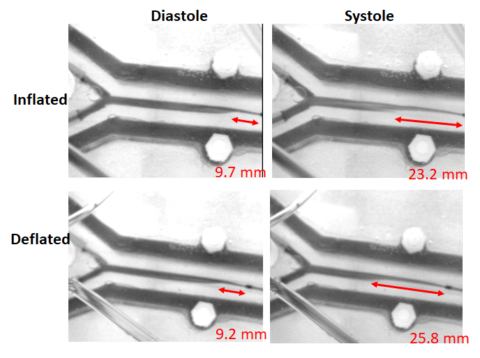
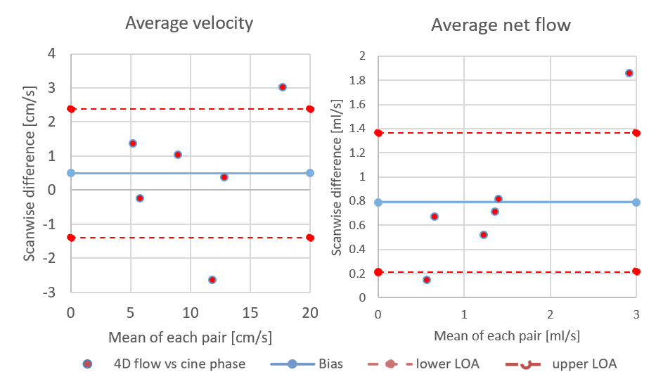
Turbulence is visualized with 4D flow and ink (Figure 1 and 2) since Re=1568 (water only) and Re=528 (33% glycerol) which yield vortices shedding frequency of 20 Hz, from St=0.19 at 40cm/s upstream. During 4D-flow, peak velocity of vortices ranges from 10 to 25cm/s in forward flow and 0 to -9cm/s in backflow. Vortex’s displacement speed is 17.7 cm/s according to the four vortices visualized. The catheter jet velocity is 43cm/s. Catheter jet length increases by 2.80-fold from diastole (9.2mm) to systole (25.8mm) (Figure 3). Bland-Altman plots of 4D flow against 2D cine phase shows an average velocity bias of 0.49 cm/s [limit of agreement=loa=1.88cm/s], average net flow bias is 0.788ml/s [loa=0.57ml/s] (Figure 4).Discussion
The oscillating flow from the cardiac cycle, the flow from the catheter, and the flow bypassing the partially inflated angioplasty balloon creates turbulence which can be visualized downstream with in-plane resolution 0.8mm in 4D Flow. These findings were corroborated by ink injection and videos, confirming that these vortices are not just artifacts. These turbulences may correspond to Karman vortex street from vortex shedding, which will be further researched. Measurement of the average velocity is reproducible either with 4D Flow or Cine Phase, i.e. 4D flow can be used to characterize turbulent flow in multiple branches of 3- and 4-mm diameter. Our in-vitro experiment can be used to refine 4D flow simulation models.The jet length triple at systole and propel aggregates forward beyond the vortices, allowing them to remain intact. In previous MRN experiments, 8% of aggregates broke (125 steering tests) after being released from the catheter, producing nontarget embolization. It might be caused by the catheter jet velocity (43cm/s), the turbulence, the success rate of the aggregate injector (failure=10% [7], tests=50) and the shear stress from the transition to smaller vessels [8].
Conclusion
Turbulence patterns which may correspond to vortex shedding, generated by pulsatile flow bypassing partially inflated balloon, can be visualized with 4D flow in phantoms mimicking hepatic arteries. These findings were verified by injecting ink in a similar flow condition. Measurement of the average flow velocity either with 4D flow or 2 cine-phase is reproducible in the phantoms with 0.8mm in plane resolution at 3T MRI. Up to now, 4D flow has dealt with large vessels such as the aorta (2.5cm), yet there is a need to better non-invasively characterize complex flow patterns in smaller vessels. In particular, the clinical translation of magnetic resonance navigation in liver chemoembolization requires detailed knowledge of flow patterns in the hepatic arteries (generally less than 5mm in diameter) after flow control using the balloon catheter.Acknowledgements
Canadian Institutes of Health Research
Siemens Healthineers, Canada
Transmedtech, Montréal, Canada
References
1. Trost, J. C., and L. David Hillis. Intra-Aortic Balloon Counterpulsation. 2006.doi:10.1016/j.amjcard.2005.11.070
2. Li, N. Magnetic Resonance Navigation for targeted embolization in a two level bifurcation phantom. , 2019.
3. Martel, S., J.-B. Mathieu, O. Felfoul, A. Chanu, E. Aboussouan, S. Tamaz, P. Pouponneau, L. Yahia, G. Beaudoin, G. Soulez, and M. Mankiewicz. Automatic navigation of an untethered device in the artery of a living animal using a conventional clinical magnetic resonance imaging system. Appl. Phys. Lett. 90:114105, 2007.
4. Michaud, F., N. Li, R. Plantefève, Z. Nosrati, C. Tremblay, K. Saatchi, G. Moran, A. Bigot, U. O. Häfeli, S. Kadoury, A. Tang, P. Perreault, S. Martel, and G. Soulez. Selective embolization with magnetized microbeads using magnetic resonance navigation in a controlled-flow liver model. Med. Phys. 46:789–799, 2019.
5. Li, N., C. Tremblay, and S. Martel. Combining oscillating flow & clinical MRI gradients for targeted therapy. , 2017.doi:10.1109/MARSS.2017.8001937
6. Chen, S.-S., and Shoei-Sheng. Flow-Induced Vibration of Circular Cylindrical Structures. Argonne, IL (United States): 1985.doi:10.2172/6331788
7. Li, N., F. Michaud, Z. Nosrati, D. Loghin, C. Tremblay, R. Plantefeve, K. Saatchi, U. Hafeli, S. M. Martel, and G. Soulez. MRI-compatible injection system for magnetic microparticle embolization. IEEE Trans. Biomed. Eng. 1–1, 2018.doi:10.1109/TBME.2018.2889000
8. Mellal, L., K. Belharet,
D. Folio, and A. Ferreira. Optimal structure of particles-based
superparamagnetic microrobots: application to {MRI} guided targeted drug
therapy. 17:, 2015.
Figures