1610
Coaxial coil modules as building blocks of individually arranged receive-only coil arrays1High Field MR Center, Center for Medical Physics and Biomedical Engineering, Medical University of Vienna, Vienna, Austria
Synopsis
Close form-fitting and adaptation of the RF coil array to the target anatomy are key for obtaining high SNR. We combine ultra-flexible coaxial coils with a modular setup to achieve form-fitting by coil flexibility and adaptive coverage of the assembled array through modularity. In this work, the robustness of the coil characteristics upon reconfiguration of three modules in different array arrangements, was investigated and demonstrated its feasibility without compromise in coil performance.
Introduction
For high signal-to-noise ratio (SNR), close form-fitting of RF coils is essential. The adaptation of the overall array size to the target anatomy enables high quality imaging. By combining flexible RF coil elements with a modular approach, the criteria can be fulfilled. To this end, we developed 4-channel receive-only RF coil modules made from single-gap coaxial coils [1,2,3] and investigated their performance in different array layouts.Methods
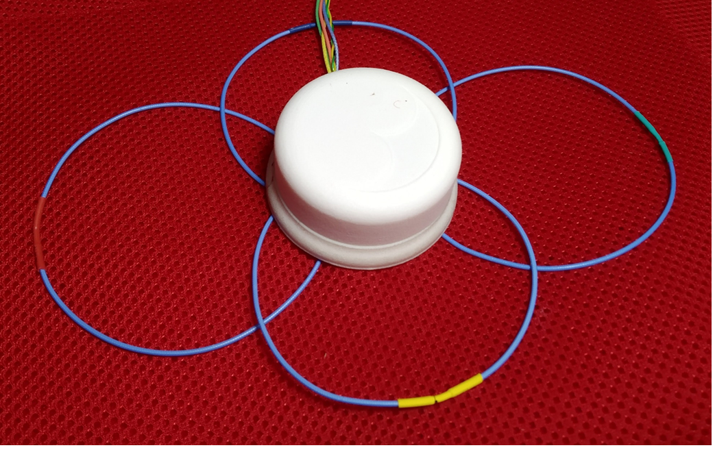
Compact modulesA module consists of four 4 coaxial coil (CC) elements, each with a diameter of 8 cm, with one gap in the outer conductor and one in the inner conductor (coil port). The CCs (also called high impedance coils [3]) were configured to operate on self-resonance at the 3T 1H Larmor frequency (123.2 MHz). The optimal overlap to minimize the mutual coupling between neighboring elements is approximately 75% of the individual coil diameter [4]. An optimized interface circuitry for single-channel 8 cm CCs consisting of tuning, matching, active detuning, and preamplifier decoupling was previously presented [5]. Based on the findings, two round double-sided printed circuit boards (PCBs) per module were designed (KiCad, kicard.org). The PCBs are stacked and connected via pins and sockets. Miniaturized low-noise preamplifiers (MwT, Fremont, USA) with a footprint of only 10.9x9.1 mm2 were used. A compact cylindrical 3D printed housing encloses the 4-ch interfaces with outlets for coils and cables (Fig. 1). Three identical modules were fabricated, each of them only weighing approximately 55 g including housing and preamplifiers.
Bench measurements
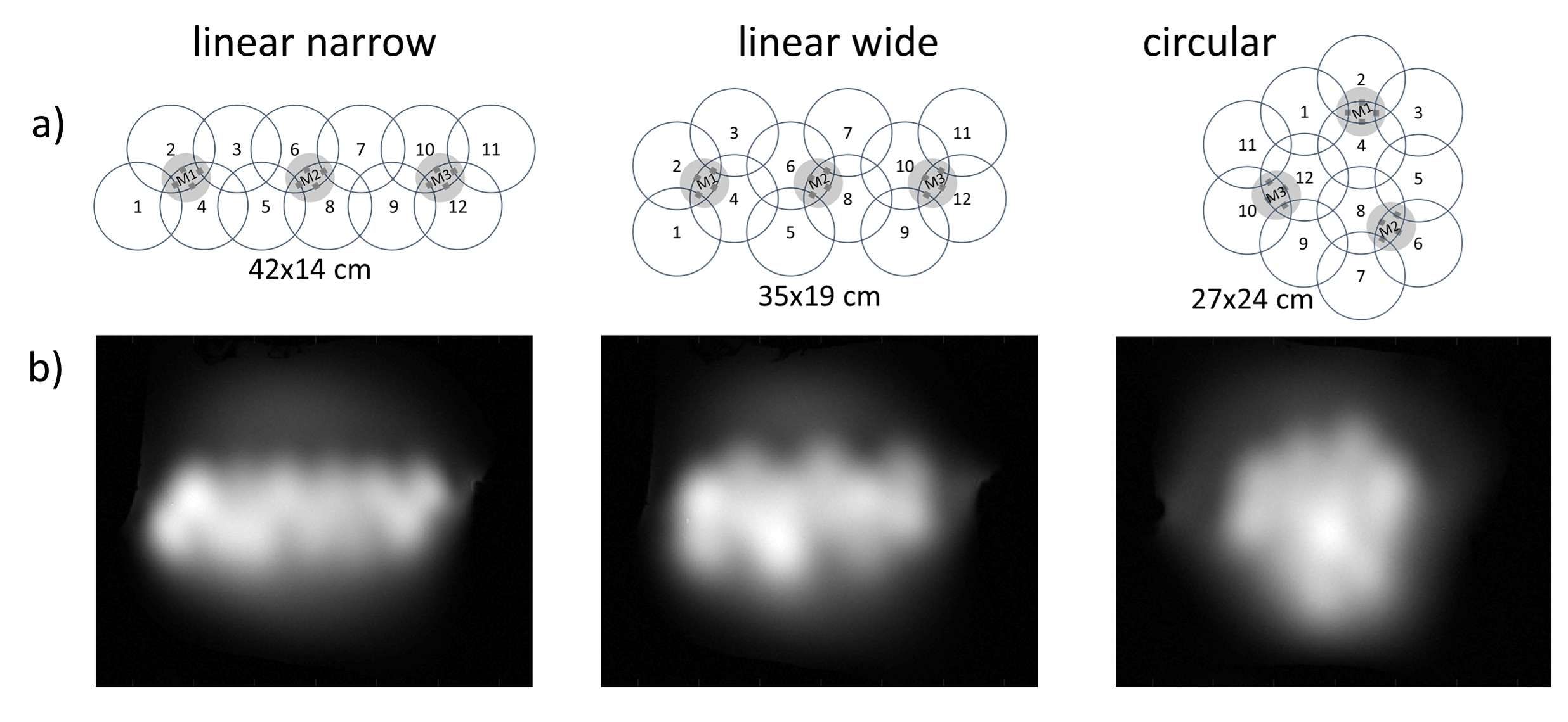
Each module (M1, M2, M3) was tuned and matched separately on a flat phantom (25L container filled with deionized water, 1.6g NaCl/L, DC conductivity ≈ 0.2 S/m, 1mL/L Magnevist) using a VNA (E5071C, Keysight Technologies, Santa Rosa, USA). A double loop probe was used to evaluate preamplifier decoupling efficiency by measuring S21 difference (ΔS21) between the states connected to the preamplifier or terminated with 50 Ω. M1, M2 and M3 were combined to a “narrow linear” (42x14 cm), to a “wide linear” (35x19 cm), and to a nearly “round” array (25 cm) as depicted in Fig. 2a. Performance tests on the bench were repeated for each 12-channel array without re-tuning and re-matching.
MR measurements
Coronal 2D GRE images (TR = 470 ms, TE = 3.23 ms, resolution 1.5x1.5x3 mm³) and noise only scans were acquired on a 3 Tesla MR scanner (Siemens Magnetom, Prisma Fit). The arrays were placed ≈ 5 mm upon the phantom.
Results
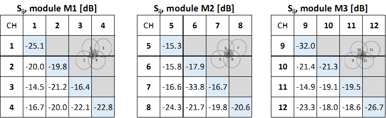
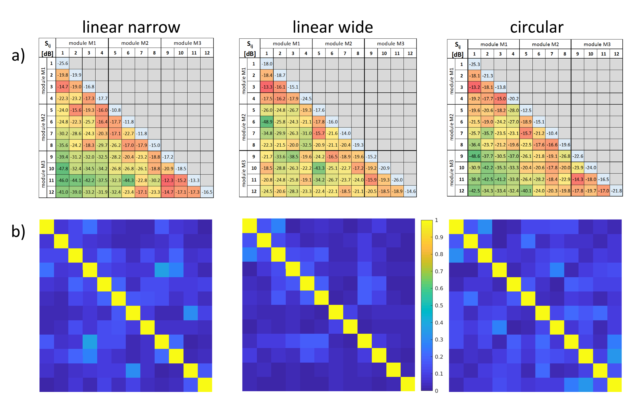
Bench performanceS-parameters of the separate modules are shown in Tab. 1. All coils are sufficiently matched (Sii < -15.3 dB) and within each module a sufficient decoupling is obtained (Sij < -14.5 dB). Maximum coupling occurs between non-overlapping elements (i.e., 1-3, 5-7, 9-11). Preamplifier decoupling was > 9.5 dB for all elements and 11.5 dB on average. S-parameters of the combined modules can be seen in Fig. 3a. Overall, a slight increase of the matching level is observed. For both linear arrays Sij of M2 increased the most. On average, the matching level from the separate modules to the combined arrays increased by 3.4 dB. Coupling of the elements increased but remained sufficiently low (Sij < -12.3 dB). Inter-module coupling increased on average only 1.4 dB for all three arrays.
MR performance
Noise correlation matrices are shown in Fig. 3b. The linear narrow and the circular array have similar noise correlation (max = 0.36, 0.33; average = 0.10, 0.11, respectively). The correlation of noise for the linear wide array is even lower (max = 0.27, average = 0.05). MR images in Fig. 2b show similar and homogeneous performance of all elements.
Discussion and Conclusion
Flexible 4-channel receive-only CC modules as building blocks for arrangement in larger arrays were presented. The modules are tuned and matched only once separately and can then be freely arranged in different configurations, only obeying the correct overlap between neighboring elements. To demonstrate possible arrangements, three basic layouts with three modules (i.e. 12-channel arrays) were presented. Performance tests on the bench, for the separate modules and for the combined modules were presented. The array S-parameters showed only minor changes compared to the isolated modules. The coil elements were sufficiently decoupled in all configurations. A fine adjustment of the coil positions is not necessary and underlines the building block method. In future applications, these modules could be rearranged in the scanner to fit different anatomic regions of interest: for instance, the same modules used for an elongated linear array for spine imaging could easily be rearranged to a compact, nearly round array for heart imaging without further adjustments. Due to the flexibility of the presented modules, form-fitted arrays could be obtained allowing close positioning to the regions of interest. The resulting arrays could be wrapped around the ROI (e.g. for knee imaging) and the array could even be enlarged (made smaller) for larger (smaller) subjects, making a set of modules a versatile multi-purpose coil.In conclusion, a proof of principle for a truly modular ultra-lightweight multi-purpose flexible receive array was demonstrated by showing three 4-channel modules arranged in different configurations.
Acknowledgements
This work was funded by the Austrian/French FWF/ANR grant, Nr. I-3618, “BRACOIL“.References
[1] L. L. Libby, "Special Aspects of Balanced Shielded Loops," Proceedings of the I.R.E. and Waves and Electrons September 1946: 641-646.
[2] H-J. Zabel, R. Bader, J. Gehring, W. J. Lorenz, " High-Quality MR Imaging with Flexible Transmission Line Resonators," Radiology 165: 857-859., 1987.
[3] B. Zhang, D. K. Sodickson, and M. A. Cloos, "A high-impedance detector-array glove for magnetic resonance imaging of the hand," Nature Biomedical Enineering 2: 570-577., 2018.
[4] P. B. Roemer, W. A. Edelstein, C. E. Hayes, S. P. Souza, and O. M. Mueller, "The NMR phased array," Magnetic Resonance in Medicine 16(2): 192-225., 1990.
[5] M. Obermann, et al., "Optimization and miniaturization of Rx-only coaxial coil interfacing," in Proc. Intl. Soc. Mag. Reson. Med. 28: 4042, 2020.
Figures