1608
New approach to Improve Sensitivity of Implantable NMR microprobe through Electrical Modelization1Univ Lyon, CNRS, Université Claude Bernard Lyon 1, Institut des Sciences Analytiques, UMR 5280, Villeurbanne, France, 2Icube Laboratory, UMR –CNRS 7357, Université de Strasbourg, Strasbourg, France, 3Grossman School of Medicine, New York University, New York, NY, United States, 4INL(Institut des nanotechnologies de Lyon), INSA (Institut National des Sciences Appliquées) Lyon, CNRS, Université Claude Bernard Lyon1, Villeurbanne Cedex, France, 5Univ Lyon, CNRS, Université Claude Bernard Lyon 1, Institut des Sciences Analytiques, UMR 5280, INSA Lyon (Institut National des Sciences Appliquées), Villeurbanne, France
Synopsis
In this study, we propose an original modelling platform 3D-TLE (Transmission Line Extractor) to determine NMR coil and microcoil performance from their geometry. Each part of our microcoil (region of interest \((ROI \sim 2µL-3µL))\), active part, Transmission Line (TL), micro-wire connection (underpass-vias) and the substrate is modelled by an electrical circuit and each contribution to the equivalent resistance is quantified. Our platform allows predicting the optimized microcoil geometry related to expected performances in terms of \(Q-factor\) and the signal-to-noise ratio \((SNR)\).
Purpose
The opportunity to predict and optimize the geometry of the coils and micro-coils from the expected performance (Q factor and SNR) would lead to the manufacture of the geometry and optimal dimensions of the micro-coils dedicated in our case to the detection of small samples and low concentrations of analytes, using localized NMR spectroscopy (MRS).Methods and results
One of the main challenges of NMR spectroscopy is to improve the sensitivity and spectral resolution in the case of weak metabolites concentration in a small region of interest (ROI \(\sim 2µL-3µL\)). One way to increase this sensitivity of detection is to miniaturize the NMR receiver. Thus, it will be adapted to the sample dimension which improves the Signal to Noise Ratio (\(SNR\)).The NMR sensitivity has been the subject of numerous studies for years. Thus, several approaches were already proposed for its optimization: use of higher field 1, and improvement of the sensitivity of the RF coil 2. For our future applications, we require highly localized observations and metabolite quantifications of a few microliters in specific tissue inside the rodent brain (mouse or rat) 3. That is why we adapted the coil to the sample dimension. This improves the magnetic field \(\frac{B_{1}}{i}\) , minimize the equivalent resistance \(R\) and enhances the \(SNR\) (Signal to Noise Ratio). We can also enhance the “Needle microcoil” performance improving the microfabrication technology after predicting an optimal microcoil geometry 4,5,6.
The microcoil sensitivity depends on \(SNR\) and the sample concentration \(([c])\):
$$S_{c}=\frac{SNR}{[c]} (1) $$ With :
$$ SNR \propto \frac{B_{1}w_{0}.B_{0}.V_{b}}{i\sqrt{k_{B}.T.R.\Delta f}} (2)$$
Where: \(w_{0}\) is the angular resonance frequency, \(B_{0}\) is the static magnetic field, \(V_{b}\) is the volume of the sample, \(\frac{B_{1}}{i}\) is the RF magnetic field by a unitary current, \(k_{B}\) is the Boltzmann constant, \(T\) is the system temperature, \(R\) is the microcoil equivalent resistance and \(\Delta f \) the bandwidth.
When the NMR microcoil is miniaturized, the sample noise becomes negligible 5. Therefore, the noise would essentially come from the microcoil 1,7.
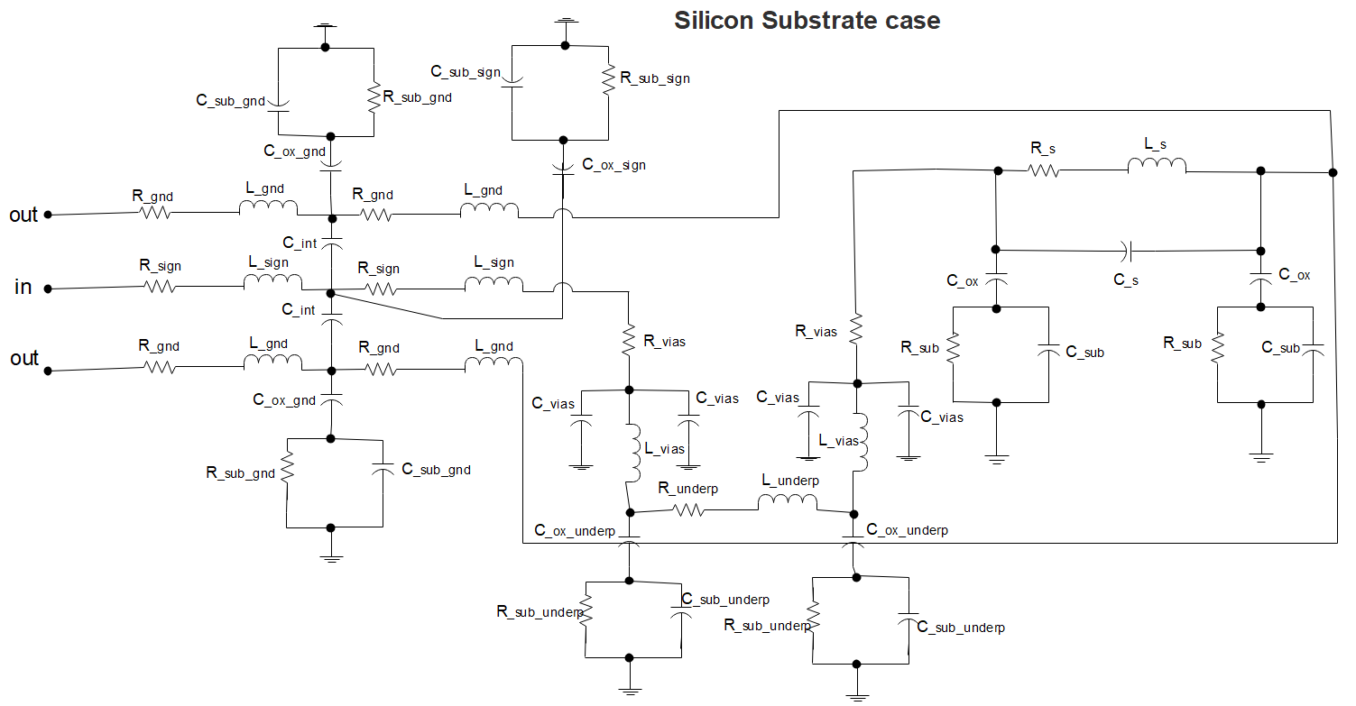
Several electrical circuits to model microcoil were proposed e.g. \(RLC\) circuit (Resistance-Inductance-Capacitor) that generally models a microcoil on a glass substrate and the \(PI\) model in case of a silicon substrate 8,9. Both previous models do not take into account the micro-transmission line (TL) and interconnection wire (e.g., underpass & vias, wire bonding, airbridge) that increases the microcoil noise and affects the \(SNR\).
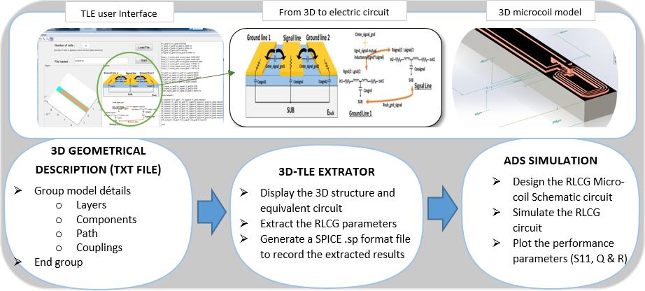
In this perspective, we propose a complete electrical circuit to model the microcoil on a glass or silicon substrate\( (figure. 2)\).
The simulation of the electric model was carried out by ADS (Advanced Design System) software; the \(S_{11}\) parameter was defined as the performance parameter criteria to study the reflection losses and calculate the quality factor \(Q\). The extraction of each electric parameter \((RLC)\) was done through 3D-TLE platform, home developed code based on MATLAB software.
This platform extracts the resistance value of a transmission line at a working frequency from \(300MHz\) to \(500MHz\), taking into account the skin and the proximity effect, the capacitive and inductive coupling between two nearby conductors, as well as the effect between the conductor wire, the substrate and the oxide layer where the metal wire is embedded10. The platform provides a user interface, where one can carry out the 3D design, and run the extraction of the \(RLC\) and the coupling parameters. The 3D modelling and conception are done by a generated SPICE file, having inside all the geometrical size parameters and the material electric property features \((figure. 1)\).
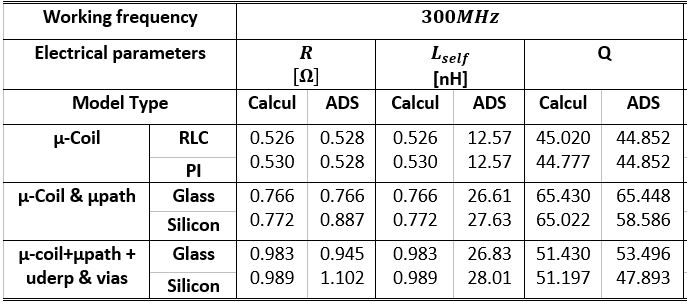
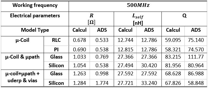
To illustrate, the impact of each part of the microprobe (micro-coil, TL, underpass & vias), on both substrates case (glass and silicon) at \(300MHz\) and \(500MHz\), \(table.1\) summarizes the ADS outcomes (the resistance \(R\), self-inductance \(L\) and \(Q\) factor from each electric model). They influence the variation of Resistance, self-inductance and the \(Q-factor\) parameter, is much understood through the global electrical circuit study.
Conclusion
To sum up and conclude, the 3D-TLE platform represents a new and powerful tool to increase NMR antenna capabilities by providing the electrical extraction parameters approach. The microcoil electrical model provides a means to quantitatively and accurately analyze the NMR antennas resistive loses and offers the possibility to quantify the contribution of each part to the NMR sensitivity estimation. Our platform allows to predict the optimized microcoil geometry related to expected performances in term of \(Q-factor\) and the signal-to-noise ratio\((SNR)\).Acknowledgements
The authors would like to thank the National Research Agency (ANR) for financial support through the ANR-16-CE19-0002-01 project and also Dr Y. Zaim Wadghiri from Grossman School of Medicine, New York University, for his help in simulating microcoils using CST MWS® software.References
1. D. I. Hoult et R. E. Richards, « The signal-to-noise ratio of the nuclear magnetic resonance experiment », Journal of Magnetic Resonance (1969), vol. 24, no 1, p. 71‑85, oct. 1976, doi: 10.1016/0022-2364(76)90233-X.
2. R. R. Ernst et W. A. Anderson, « Application of Fourier Transform Spectroscopy to Magnetic Resonance », Review of Scientific Instruments, vol. 37, no 1, p. 93‑102, janv. 1966, doi: 10.1063/1.1719961.
3. A. Kadjo et al., « In vivo animal NMR studies using implantable micro coil », in 2008 IEEE International Workshop on Imaging Systems and Techniques, Chania, Islandof Crete, sept. 2008, p. 294‑296, doi: 10.1109/IST.2008.4659987.
4. N. Baxan et al., « Limit of detection of cerebral metabolites by localized NMR spectroscopy using microcoils », Comptes Rendus Chimie, vol. 11, no 4‑5, p. 448‑456, avr. 2008, doi: 10.1016/j.crci.2007.07.002.
5. D. I. Hoult, « The NMR receiver: A description and analysis of design », Progress in Nuclear Magnetic Resonance Spectroscopy, vol. 12, no 1, p. 41‑77, janv. 1978, doi: 10.1016/0079-6565(78)80002-8.
6. C. Massin, C. Azevedo, N. Beckmann, P. A. Besse, et R. S. Popovic, « Magnetic resonance imaging using microfabricated planar coils », in 2nd Annual International IEEE-EMBS Special Topic Conference on Microtechnologies in Medicine and Biology. Proceedings (Cat. No.02EX578), Madison, WI, USA, 2002, p. 199‑204, doi: 10.1109/MMB.2002.1002313.
7. T. L. Peck, R. L. Magin, et P. C. Lauterbur, « Design and Analysis of Microcoils for NMR Microscopy », Journal of Magnetic Resonance, Series B, vol. 108, no 2, p. 114‑124, août 1995, doi: 10.1006/jmrb.1995.1112.
8. K. B. Ashby, W. C. Finley, J. J. Bastek, S. Moinian, et I. A. Koullias, « High Q inductors for wireless applications in a complementary silicon bipolar process », in Proceedings of IEEE Bipolar/BiCMOS Circuits and Technology Meeting, Minneapolis, MN, USA, 1994, p. 179‑182, doi: 10.1109/BIPOL.1994.587889.
9. Yu Cao et al., « Frequency-independent equivalent circuit model for on-chip spiral inductors », in Proceedings of the IEEE 2002 Custom Integrated Circuits Conference (Cat. No.02CH37285), Orlando, FL, USA, 2002, p. 217‑220, doi: 10.1109/CICC.2002.1012800.
10. Y. Ma, « Modèles compacts électroniques du premier ordre et considération de bruit pour les circuits 3D », Université de Lyon 1, INSA -Lyon, Villeurbanne, France, 2018.
Figures
\((a)\)
\(Table 1. (a), (b)\). Summary of RLQ electrical parameters from a different model of microcoil, all of them tuned at 300MHz (a) and 500MHz (b).
\((b)\)
\(Table 1. (a), (b)\). Legend: µ-coil = active part, µ-coil & µpath = Active part +TL, µ-coil+µpath+underpass & vias = complete model