1606
Universally Sized, High-Resolution and ASSET Optimized AIR Cervical Coils Combined with a 48-Channel Head Coil for 3T MRI1GE Healthcare Coils, Aurora, OH, United States, 2GE Healthcare, Waukesha, WI, United States, 3Haeundae Paik Hospital, Busan, Korea, Republic of, 4Severance hospital, Yonsei University, Seoul, Korea, Republic of, 5Hospital for Special Surgery, New York, NY, United States
Synopsis
Conventional high density phased-array head/neck coils are designed to tightly conform to head/neck region to increase SNR and accommodate higher acceleration, which in turn limits space and their use for larger patients. This study shows results for two different universally sized AIR (Adaptive Imaging Receive) neck/cervical spine coils combined with a 48-Channel head coil to provide higher SNR and improved acceleration compared to a conventional coil. 3T MRI setups to image the head/neck, carotids and cervical spine were designed and constructed. Phantom measurements and high-resolution in vivo imaging were performed to demonstrate design performance.
INTRODUCTION
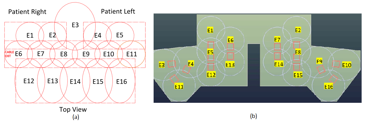
Typically, a tightly fit rigid head/neck/cervical spine or rigid head/neck array, combined with a flexible cervical spine array, is used for brain, neurovascular and cervical spine MRI. Some body habiti do not fit these types of close-fitting coil designs. These coils also do not generally provide deep depth or high-resolution of the carotid arteries and cervical nerves due to the large distance between coil elements and targeted anatomy. High acceleration factors are also not practical due to the low SNR and the number of elements in the field of view (FOV). Coil positioning can also be challenging. In this study, universally sized AIR neck/cervical spine coils combined with a 48-Channel head coil for carotid, head/neck and cervical spine MRI are presented. Two prototypes of a 16-Channel phased-array neck/cervical spine coil (Fig. 1 (a) and (b)), combined with a 48-Channel head coil, were constructed on foam and flexible fabric materials (fitting more than 99th-percentile US male) with AIR technology. These coils were then evaluated on phantoms and human volunteers under an IRB-approved protocol.METHODS
A range of head and body habiti were evaluated to ensure the coil accommodates head and body sizes fitting more than the 99th-percentile US male. The 16-Channel neck/cervical spine anterior setup (prototype1, Fig. 2 (a)) contains ten 8cm AIR loops for the carotid region, five 10.6cm loops for the chest region and one 13cm for the chin region. The 16-Channel neck/ cervical spine posterior setup (prototype2, Fig. 2 (b)) contains ten 12cm AIR loops for the carotid region, six 14cm loops for the chest and chin regions. The AIR coil loops are made from highly flexible 1.0 mm conductor optimized for zero reactance and low loss with no lumped components at 127.73 MHz. The electronics module including the preamplifier, decoupler, matching, and baluns is connected to the new AIR coil loop. Nearest neighboring elements were decoupled by overlapping and next nearest neighbor and more distant elements were decoupled by preamplifiers which has exceptionally low noise and is tolerant of a wide range of loop loading conditions. Full coverage of the head, neck and cervical spine regions were achieved by 64 elements located in a posterior head (32-Channel), an anterior head (16-Channel) and flexible neck/cervical spine flaps (16-Channel). The flexible materials and AIR Coil loops for the neck/cervical spine coils provide a light-weight flexible conforming coverage (Fig. 1 (a) and (b)). These coils shall support a 1D acceleration factor of 3 (R=3) with ASSET and a Multi-Band acceleration factor of 3 (SI) in FOV 30 cm. AIR loops are interposed between two thermoplastic-coated thin fabrics (1mm). A medical-grade foil was used as the coil cover sleeve for biocompatibility and a water seal. SNR and max g-factors for R=2, 3, 4 were measured in loading shell phantom. The coil was developed and tested on a 3T GE Premier scanner (GE Healthcare, Aurora, Ohio USA). Volunteers were imaged at the Hospital for Special Surgery (New York, USA) and GE Healthcare (Waukesha, WI and Aurora, OH).RESULTS
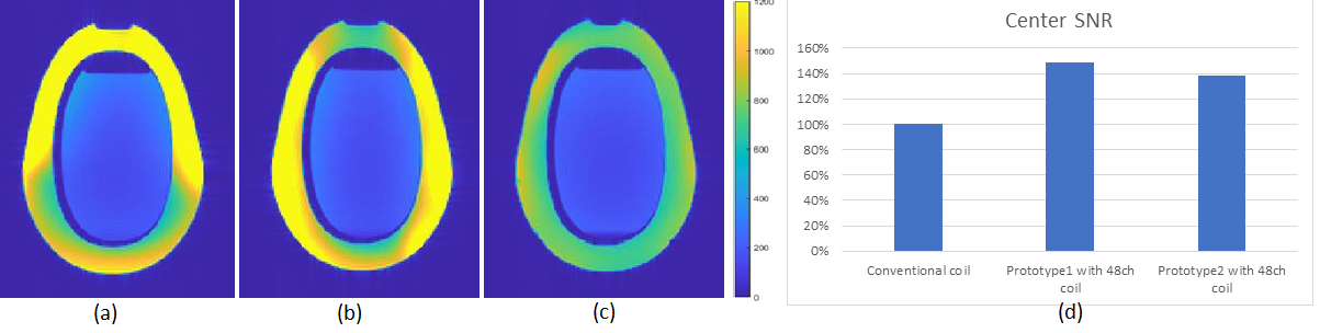
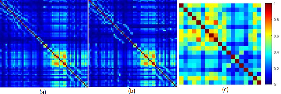
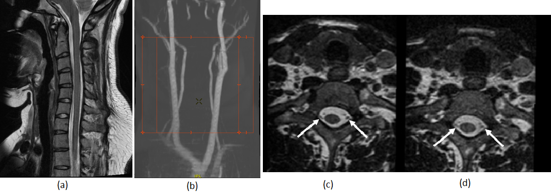
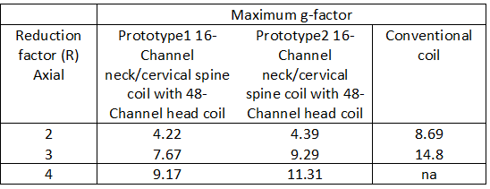
The 16-Channel neck/cervical spine prototype1 coil with the 48-Channel head coil provided deeper depth, higher resolution and highly accelerated loading phantom images compared to the 16-Channel neck/cervical spine prototype2 coil with 48-Channel head coil and a conventional coil due to the optimized loop layout and proximity to the targeted anatomy. Figure 3 (a), (b) and (c) show the loading phantom SNR maps using optimal reconstruction method for the 16-Channel neck/cervical spine prototype1 with the 48-Channel head coil, the 16-Channel neck/cervical spine prototype2 with the 48-Channel head coil and the conventional coil. Figure 3 (d) shows the loading phantom SNR comparison results. Figure 4 (a), (b) and (c) show the noise correlation matrices. Table 1 summarizes the maximum g-factor at 2, 3 and 4 for 1D acceleration in the axial plane. High-resolution in vivo imaging was performed using the optimized neck/cervical spine prototype1 coil with 48-Channel head coil. This 16-Channel neck/cervical spine prototype1 coil with the 48-Channel head coil accommodates a large FOV for cervical spine and neck MRA exams (Fig. 5 (a) and (b)). It also supported high spatial resolution (0.7 mm isotropic) 3D T2-weighted FSE imaging with visually higher SNR (Fig. 5 (c)) as compared to a conventional coil setup (Fig. 5 (d)).DISCUSSION
The loading shell phantom results for B1 sensitivity mapping and g-factors are matched to the results of the in vivo images.CONCLUSION
The universally sized 16-Channel AIR neck/cervical spine prototype coils with a 48-Channel head coil that accommodate more than the 99th-percentile US male provide ultra-flexibility, comfort, high-resolution and accelerated imaging with AIR technology including highly flexible conductor, miniaturized electronics, exceptionally low noise preamp, and light-weight mechanical materials. The head/neck, carotid and cervical spine can be visualized on large field isotropic images (while still maintaining high spatial resolution) that can then be reformatted into multiple planes for analysis. The optimized 16-Channel AIR neck/cervical spine prototype coils with a 48-Channel head coil provided better SNR and improved acceleration compared to the conventional coil in a small sample of volunteers.Acknowledgements
We also thank Saban Kurucay, Dan Weyers, Dan Chirayath and Mohamed El-Demerdash from GE Healthcare for their continued support.References
1. Zhang Q., et al., Comparison of four MR carotid surface coils at 3T. PLoS ONE 14(3): e0213107.
2. Kim Y.C., et al., Novel 16-Channel Receive Coil Array for Accelerated Upper Airway MRI at 3 Tesla. MRM, 2011; 65:1711–1717.
3. Stickle Y.J., et al., Universal Size-Optimized 48-Channel Phased-Array Receive Head Coil for 3T Clinical fMRI/Silent. Proceedings ISMRM 2017, 1226.
4. Rossman P., et al., Characterization of a new ultra-flexible low-profile RF receive coil technology. Proceedings ISMRM 2017, 763.
5. Vasanawala S.S., et al., Development and Clinical implementation of very light weight and highly flexible Air technology arrays. Proceedings ISMRM 2017, 755.
6. Roemer P.B., et al., The NMR phased array. MRM, 1990; 16(2):192-225.
7. Pruessmann K.P., et al., SENSE: sensitivity encoding for fast MRI. MRM, 1999;42:952–962.
Figures
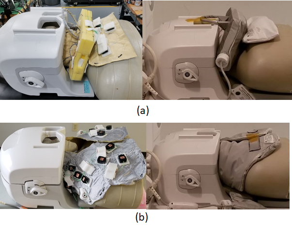
Fig. 1. Universally sized AIR 64-Channel
phased array head neck coils for carotid, head/neck and cervical spine MRI (a) Prototype1 16-Channel neck/cervical spine
anterior setup coil assembly with 48-Channel head coil (b) Prototype2
16-Channel neck/cervical spine posterior setup coil assembly with 48-Channel
head coil