1605
An Integrated Radio-Frequency/Wireless (iRFW) Coil Design for Wireless Q-Spoiling During MR Imaging
Jonathan Cuthbertson1,2, Trong-Kha Truong1,2, Jasmine Chen1,2, Fraser Robb3, Allen W. Song1,2, and Dean Darnell1,2
1Medical Physics Graduate Program, Duke University, Durham, NC, United States, 2Brain Imaging Analysis Center, Duke University, Durham, NC, United States, 3GE Healthcare, Aurora, OH, United States
1Medical Physics Graduate Program, Duke University, Durham, NC, United States, 2Brain Imaging Analysis Center, Duke University, Durham, NC, United States, 3GE Healthcare, Aurora, OH, United States
Synopsis
The integrated RF/wireless coil design allows for simultaneous MR image acquisition and wireless data transfer with the same coil element in order to reduce the number of wired connections in the scanner. Here, we use this coil design to wirelessly transmit the scanner trigger signal to perform the Q-spoiling required for MR imaging. Proof-of-concept experiments in a phantom showed that this coil design was able to accurately and reliably transmit the scanner trigger from the adjacent console room to a WiFi-enabled module in the scanner bore, while having minimal impact on the image SNR or wireless performance.
Introduction
Integrating wireless data transfer in an MRI scanner would allow for the reduction of wired connections between RF coil arrays and the scanner electronics, which take up space within the scanner bore and add to the cost and complexity of the system1,2,3,4. To enable wireless MR data transfer with an RF coil array, control signals (e.g., the Q-spoiling scanner trigger to RF-isolate the preamplifier during the scanner transmit cycle) must be transferred from the scanner to the array according to the pulse sequence timing. Recent bench-top measurements of multiple antenna designs to transmit the control signals suggest that a reflected biquad coil loop design could potentially provide the best wireless connection for Q-spoiling, but would require modifications to the scanner5,6. In contrast, a novel integrated RF/wireless (iRFW) coil design was previously developed, in which RF currents at the Larmor frequency (e.g., 127 MHz for 3T scanners) and in a wireless communication band (e.g., 2.4 GHz for Wi-Fi) flow on the same coil for simultaneous MR image acquisition and wireless data transfer, respectively, without requiring any scanner modifications or additional antenna systems within the scanner bore1. Previously, the iRFW coil design has been used for simultaneous imaging and wireless control of multiple peripheral systems (e.g., wireless localized B0 shimming2,3, wireless respiratory tracking3, and wireless physiological motion monitoring with an ultrasound sensor7). In this work, the iRFW coil design is further developed to wirelessly perform the Q-spoiling required for MR imaging. Specifically, the iRFW coil design and an onboard Wi-Fi transceiver module are used to wirelessly receive control signals from the MRI scanner trigger to detune the receive coil element by activating a PIN diode during the transmit cycle.Methods
First, a 10-cm diameter RF coil element was modified into an iRFW coil element by adding custom 127-MHz (Fig. 1, red) and 2.4-GHz (Fig. 1, orange) band-stop filters between the coil element and the Wi-Fi transceiver module and preamplifier, respectively, to prevent RF losses incurred to both of them in their frequency bands1. Next, the coil element was further modified for wireless Q-spoiling by placing a PIN diode between the 2.4-GHz band-stop filter and the preamplifier (Fig. 1, blue). This PIN diode is wirelessly activated by applying a DC voltage from the RF-isolated Wi-Fi module during the scanner transmit cycle. Specifically, wireless Q-spoiling is performed by sending a wireless command initiated by the scanner trigger from a computer in the console room to the on-board Wi-Fi module attached to the coil, which then applies a DC voltage to the PIN diode to detune the coil element for the duration of the transmit cycle.Two proof-of-concept experiments were performed to verify that wireless Q-spoiling with the iRFW coil did not degrade its image quality or wireless performance. First, a time series of 76 gradient-echo EPI images (as used in fMRI experiments) was acquired with the coil on a water phantom using either wired or wireless Q-spoiling, which was achieved by applying an activation voltage to the PIN diode with either the conventional wired connections from the scanner or the Wi-Fi module GPIO, respectively. The SNR of the mean image and the temporal SNR (TSNR) of the image time series were then calculated for both Q-spoiling methods to evaluate their image quality. During this experiment, the PIN diode activation and scanner trigger voltages were measured simultaneously with an oscilloscope to verify that the Wi-Fi module could provide a similar signal as the scanner for Q-spoiling. Second, the Wi-Fi radiated power pattern was measured in a fully anechoic chamber with and without an activation voltage applied to the PIN diode to verify that the wireless performance would not be degraded during the scanner transmit cycle.
Results
The iRFW coil was able to reliably apply an activation voltage to the PIN diode for wireless Q-spoiling (Fig. 2, blue) that was similar to the voltage applied by the scanner during conventional wired Q-spoiling (Fig. 2, purple). Additionally, the SNR and TSNR of the coil averaged over the phantom were similar for wired Q-spoiling (75.3 and 53.1) and wireless Q-spoiling (75.0 and 54.4) (Fig. 3). Finally, wireless Q-spoiling with the iRFW coil showed no impact on the Wi-Fi center frequency 3D (Fig. 4A) or principal plane (Fig. 4B) radiated power gain patterns, which determine its wireless performance. Further, the radiated power of the coil across the entire Wi-Fi frequency band changed by <1% when a voltage was applied to the diode for Q-spoiling relative to the same unbiased diode measurement.Discussion and Conclusion
This work demonstrates that the integrated RF/wireless coil design can reliably perform wireless Q-spoiling for MR image acquisition without degrading image quality relative to the conventional Q-spoiling method. Additionally, the wireless performance of the coil is maintained throughout the MRI scan, which is critical to protect the MR preamplifiers during the scanner transmit cycle. Expanding upon these results, we envision that the wirelessly transmitted signals that correspond to the scanner trigger could possibly be used to activate on-board RF switching to enable wireless power harvesting or to improve the syncing of fMRI stimuli and subject responses with the timing of the MR image acquisition.Acknowledgements
This work was in part supported by GE Healthcare and grants R01 NS075017 and R01 EB028644 from the National Institutes of Health.References
- Darnell D et al. Integrated radio-frequency/wireless coil design for simultaneous MR Image acquisition and wireless communication. Magn. Reson. Med. 2019;81:2176-83
- Cuthbertson J et al. A 4-Channel iPRES-W Coil Array for Simultaneous MR Image Acquisition and Wirelessly-Controlled Localized B0 Shimming of the Spinal Cord. Proceedings of the ISMRM, May 2019, Montreal; pg. no. 1489
- Cuthbertson J et al. Dual-Stream iPRES-W Head Coil Array for MR Imaging, Wireless Respiratory Tracking, and Wireless Localized B0 Shimming. Proceedings of the ISMRM, August 2020, Virtual Conference; pg. no. 1262
- Aggarwal K et al. A Millimeter-Wave Digital Link for Wireless MRI. IEEE Trans Med Imaging 2017;36(2);574-83
- Lu JY et al. Wireless Q-spoiling of Receive Coils at 1.5T MRI. Proceedings of the ISMRM, April 2017, Honolulu; pg. no. 4297
- Lu, Jy et al. Antenna Design for Wireless Clock Syncing and Q-spoiling in MRI. Proceedings of the ISMRM , June 2018, Paris; pg. no. 28
- Willey D et al. Integrated RF/Wireless Coil and Ultrasound-Based Sensors to Enable Wireless Physiological Motion Monitoring in MRI. Proceedings of the ISMRM, August 2020, Virtual Conference; pg. no. 1282
Figures
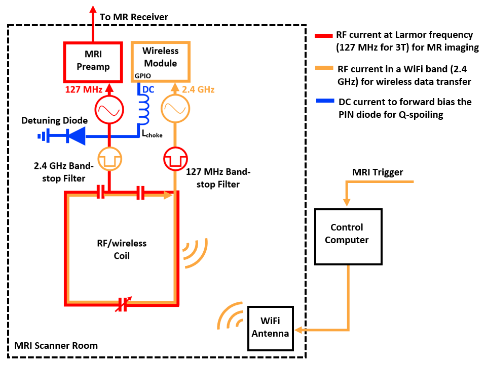
Figure 1: RF
currents flow on the integrated RF/wireless coil design for simultaneous MR
image acquisition (red) and wireless data transfer (orange), while a DC voltage
(blue) is applied to the PIN diode from a GPIO pin from the Wi-Fi transceiver module
for Q-spoiling.
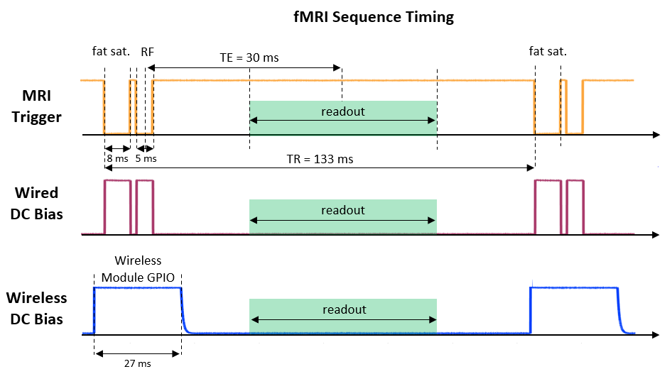
Figure 2: Diagram of the fMRI pulse sequence
showing the timing of the MRI scanner trigger (orange), which was used for
detuning the iRFW coil, either by using conventional wired connections (purple)
or by wirelessly transmitting a digital signal corresponding to the trigger for
wireless Q-spoiling (blue).
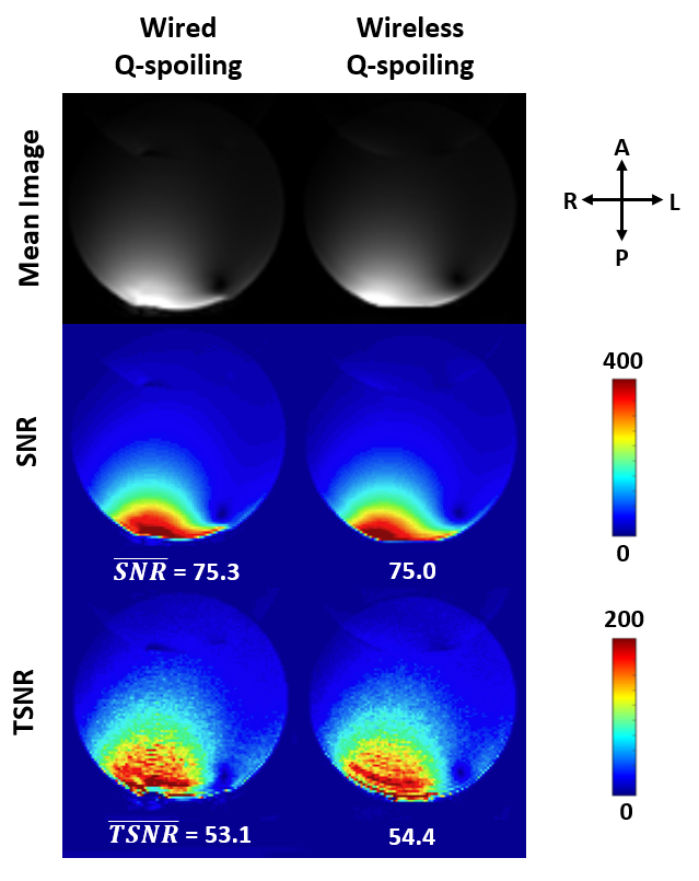
Figure 3: Gradient-echo
EPI mean images, SNR maps of the mean images, and temporal SNR (TSNR) maps of
the image time series acquired in a water phantom, showing no degradation in
image quality for wireless Q-spoiling using the iRFW coil compared to
conventional wired Q-spoiling.
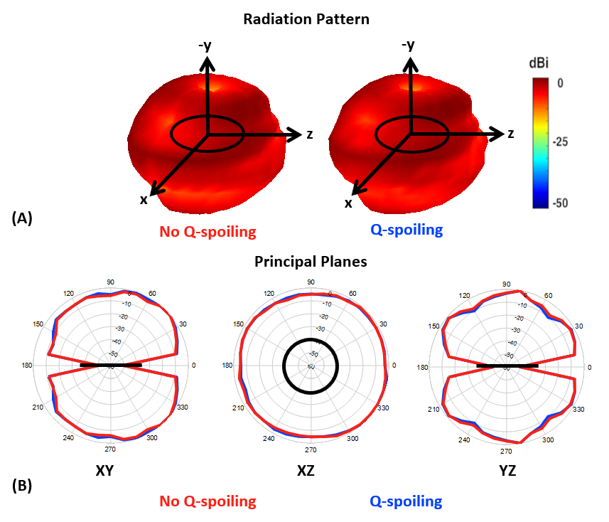
Figure 4: The iRFW coil’s 3D radiated power (A)
and the radiated power in the principal planes (B) show minimal change when
the PIN diode is not activated (during the receive cycle; red line) vs. activated
for Q-spoiling (during the transmit cycle; blue line).