1604
Design of an over-overlapped wearable 3T pelvic phased array using a capacitor-terminated coaxial coil1Vanderbilt University Institute of Imaging Science, Vanderbilt University Medical Center, Nashville, TN, United States, 2Department of Radiology and Radiological Sciences, Vanderbilt University Medical Center, Nashville, TN, United States, 3Department of Radiology and Biomedical Imaging, Yale University School of Medicine, New Haven, CT, United States
Synopsis
Prostate cancer is one of the leading causes of cancer death among men in the US. MRI is a useful tool to assess the presence and extent of prostate cancer, and diagnostic accuracy relies on acquiring images with high SNR. We aimed to improve the performance of such arrays by using flexible coaxial coil technology and an over-overlapping layout to increase the number of coil elements without sacrificing coil size.
Purpose:
Prostate cancer is the most common cancer and one of the leading causes of cancer death among men in the US1. Multiparametric magnetic resonance imaging (mpMRI) is an accepted and widely used tool for prostate cancer diagnosis, biopsy-guidance, staging, therapy planning and delivery, and post treatment surveillance. The signal-to-noise ratio (SNR) in prostate MRI remains an area to be improved on, especially for high-B value diffusion weighted images. Although endorectal coils (ERC) have excellent SNR in the prostate, their use increases patient setup time and discomfort, and distorts the anatomy, which may negatively impact the diagnostic value of the MRI images. It has been demonstrated that a pelvic phased-array coil can provide comparable imaging quality and diagnostic accuracy by using recently-developed arrays with up to 16 or 18 elements2,3. We aimed to improve the performance of such arrays by using flexible coaxial coil technology and an over-overlapping layout4 to increase the number of coil elements without sacrificing coil size.Methods:
Concept:Coaxial coils5-7 were chosen as the basic array element due to their flexibility and ease of building. A standard two-gap coaxial coil has two opposite gaps; one is in the outer conductor and the other is in the inner conductor (Figure 1A). The resonant frequency of the coaxial coil was determined by the coil diameter and materials properties (wire and substrate diameter, dielectric permittivity) as shown in Figure 1B. When using commercial RG178 coaxial cables to build such coils, their diameter is limited to 7.8 cm at 128 MHz (Larmor frequency of 3 T). For prostate imaging, however, the region of interest is located deep in the body and an optimal coil diameter is ~10 cm8. To solve this problem, the outer conductor at the feed port was broken and replaced with a capacitor (Ct in Figure 1C) so the resonant frequency can be increased and is adjustable (Figure 1D). One major challenge of flexible or wearable coils is that the overlapping area varies as coils are bent at different angles or even folded6,9. In this work, Ct can form a Π-shaped matching circuit with series capacitors Cm to improve preamplifier decoupling performance.
Simulation validation
To validate that the resonant frequency is higher than a standard coaxial coil and can be adjusted by varying the terminated capacitance, we simulated a 10-cm-diameter circular coil in Ansys HFSS (Canonsburg, PA, USA). Similar to the practical case, a double pick-up-probe was placed several centimeters away from the coil to detect the resonant frequency. To accommodate more elements for the given coverage, we employed an over-overlapping geometry (40%) for all CTC coils. The preamplifier decoupling technology becomes critical as the unwanted inductive coupling arises in such a layout. Therefore, we evaluated the preamplifier decoupling effect in the CTC coil and compared it to a conventional loop coil with three distributed capacitors and one parallel matching capacitor. This effect was evaluated in two ways: first, the resonant peak difference between a 50-ohm-load and preamplifier-load, and second, the receive sensitivity distortion compared to an ideal single coil.
Results:
Resonate frequency vs. CtFigure 2 plots the simulated resonant frequency versus Ct and its comparison with the calculation. The consistency of calculated and simulated results also demonstrates the accuracy of the equation in Figure 1D. It is clear that the resonant frequency can be easily adjusted to 128 MHz by setting Ct to 15pF.
Preamplifier decoupling effects on receive sensitivity (B1-)
Figure 3 plots the resonant peak difference (S21) that can be seen as the current-suppression or preamplifier decoupling ability. For the ideal case where the real part of the preamplifier input impedance is zero (Re[Zin] = 0 Ω), both the conventional coil and the CTC coil can achieve excellent decoupling, with ΔS21 of ~30 dB. Note the residual coupling is attributed to eddy current effects and cannot be removed by preamplifier decoupling. In the real case, Re[Zin] is typically 2-5 ohms depending on the manufacturer. Therefore, this non-ideal R[Zin] will decrease the quality factor of the blocking circuit and decrease preamplifier decoupling performance. But it is interesting that the CTC coil still has 27 dB preamplifier decoupling with Re[Zin] = 5ohm, while that of the conventional coil is only 15 dB. This phenomenon was also found in the receive sensitivity (B1-) where the CTC coil has almost the same B1- values at the 10-cm-deep region with Re[Zin] = 5ohm (0.3288/0.4164 vs. 0.3025/0.3983 µT/√W for the left/right coil), while those of the conventional coil exhibits considerable B1- decrease over the same region (0.3234/0.4001 vs. 0.2333/0.3633 µT/√W for the left/right coil), as shown in Figure 4.
Discussions:
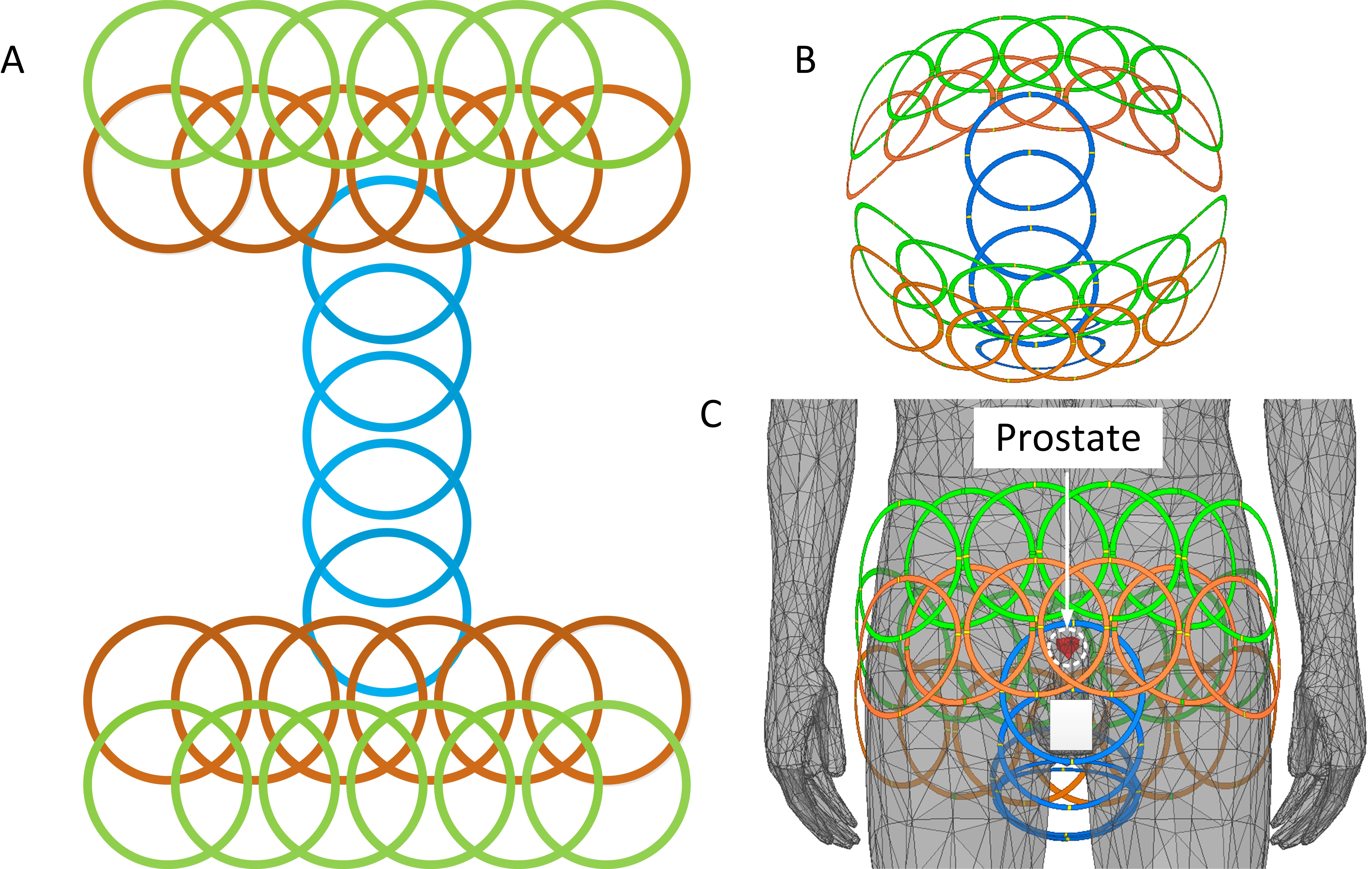
Based on our simulation results, the Capacitor-Terminated Coaxial (CTC) coil is the best candidate for prostate imaging where a wearable, size-optimized, high-density array is desired. Figure 5 shows planar unfolded (Figure 5A) and three-dimensional (Figures 5B-C) views of the coil layout of an over-overlapped 29 channel array. Future studies will focus on the coil fabrication and testing to prove the simulation results.Acknowledgements
No acknowledgement found.References
1. Siegel R, Ma J, Zou Z, Jemal A (2014) Cancer statistics, 2014. CA Cancer J Clin 64:9-29
2. Baur AD, Daqqaq T, Wagner M, Maxeiner A, Huppertz A, Renz D, Hamm B, Fischer T, Durmus T. T2-and diffusion-weighted magnetic resonance imaging at 3 T for the detection of prostate cancer with and without endorectal coil: an intraindividual comparison of image quality and diagnostic performance. European Journal of Radiology. 2016 Jun 1;85(6):1075-84.
3. O’Donohoe RL, Dunne RM, Kimbrell V, Tempany CM. Prostate MRI using an external phased array wearable pelvic coil at 3T: comparison with an endorectal coil. Abdominal Radiology. 2019 Mar 1;44(3):1062-9.
4. Lu M, Gore JC, Yan X. Over-overlapped loop arrays: A numerical study. Magnetic Resonance Imaging. 2020 Oct 1;72:135-42.
5. Yang X, Zheng T, Wu Y, Finnerty M, inventors; QUALITY ELECTRODYNAMICS LLC, assignee. Coaxial cable magnetic resonance image (MRI) coil. United States patent US 9,678,180. 2017 Jun 13.
6. Zhang B, Sodickson DK, Cloos MA. A high-impedance detector-array glove for magnetic resonance imaging of the hand. Nature biomedical engineering. 2018 Aug;2(8):570-7.
7. Nohava L, Czerny R, Obermann M, Pichler M, Frass-Kriegl R, Felblinger J, Ginefri JC, Laistler E. Flexible multi‐turn multi‐gap coaxial RF coils (MTMG‐CCs): design concept and bench validation. InProceedings of the 27th Annual Meeting of ISMRM, Montreal, Canada 2019 (p. 0565).
8. Wang J, Reykowski A, Dickas J. Calculation of the signal-to-noise ratio for simple surface coils and arrays of coils [magnetic resonance imaging]. IEEE transactions on biomedical engineering. 1995 Sep;42(9):908-17.
9. Vasanawala SS, Stormont R, Lindsay S, Grafendorfer T, Cheng JY, Pauly JM, Scott G, Guzman JX, Taracila V, Chirayath D, Robb F. Development and clinical implementation of next generation very light weight and extremely flexible receiver arrays for pediatric mri. arXiv preprint arXiv:1705.00224. 2017 Apr 29.
Figures