1603
Flexible Body Coil for Vertical Field MRI using Loop/CRC RF Coil Array1Healthcare Business Unit, Hitachi, Ltd., Tokyo, Japan, 2Hitachi Healthcare Americas, Twinsburg, OH, United States
Synopsis
To improving the SNR and the usability in the vertical field MRI(Open MRI), a flexible body(spine/torso) coil has been developed. The coil consists of loop/CRC hybrid multi-channel array (LCA). The performance of the coil was evaluated in phantom experiment at 1.2T vertical field MRI. The SNR of the coil using LCA was 46% better than a conventional body coil. This technique will contribute to improve the performance of the vertical field MRI.
Introduction
A multi-channel RF-array coil obtains high SNR by arranging the coils in high density on the surface of the subject [1-3]. In horizontal field MRI, multi channelization has progressed rapidly because loop coils can be placed freely on the surface of the subject. On the other hand, in vertical field MRI(Open MRI), multi channelization has not progressed so far because the placement of the loop coils having much sensitivity are limited and they could not be placed freely [4]. Therefore, it was considered that the loop coil could not be arranged at high density, and a large solenoid coil surrounding the subject which has high sensitivity in the deep object region was used instead. However, the array coils using the solenoid coils cannot change their shape easily, that is the cause of reduced SNR and usability. To alleviate this problem, we have developed a loop/CRC (Counter Rotating Current) hybrid multi-channel array (LCA) RF coil and body (spine/torso) coil using LCA for 1.2T vertical field MRI.Methods
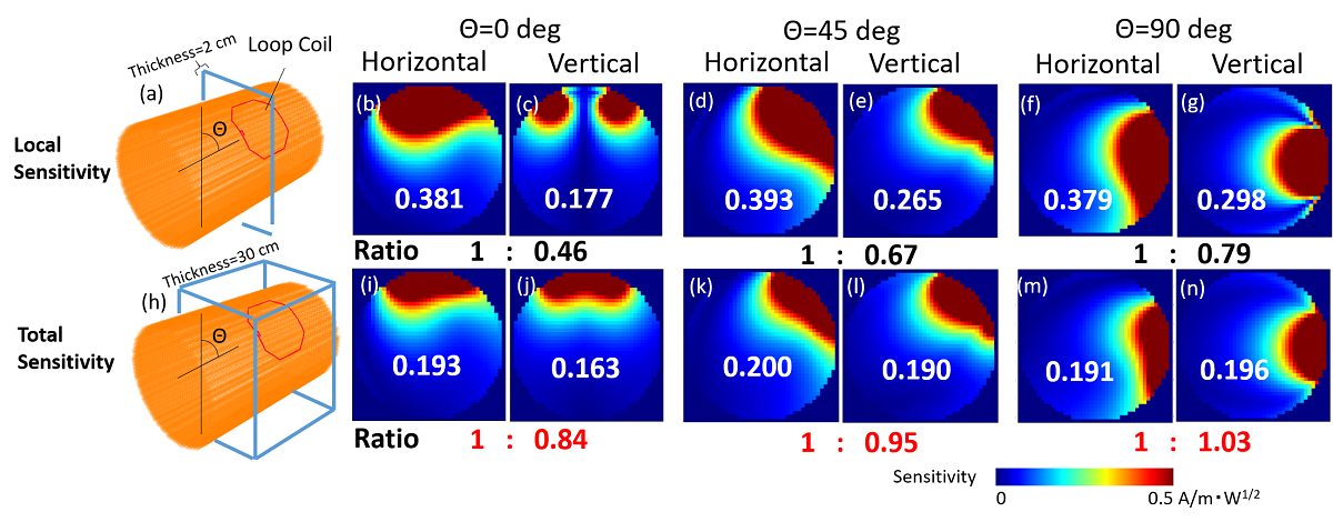
The basic configuration of the developed LCA coil is shown in Fig. 1 (a). The LCA consists of four loop coils and a CRC coil that compensates for the lack of sensitivity of loop coils. In vertical field MRI, the loop coil was considered to have poor sensitivity because there is a region where sensitivity cannot be obtained depending on the orientation of the coil (Fig. 2(c)). However, we found by RF coil simulator [5] that the total sensitivity of loop coils in vertical and horizontal MRI were not much different in a large region of interest. Figure 2 shows angle dependence of sensitivity maps of a loop coil at horizontal and vertical field MRI. Figure 2(i-n) shows that the total sensitivity is not as different as the local sensitivity. Therefore, the loop coil whose sensitivity was compensated by a CRC coil (LCA coil) will have the same sensitivity as a loop array coil for horizontal field MRI. Figure 1(a,b) shows Element diagrams of a developed torso coil and a spine coil using LCA coils. Each coil consists of 6 ch loop coils and 2 ch CRC coils. The length of the loop coil in the axial direction was shortened to minimize the area of signal loss and the loop coil is compensated with the CRC coil. And distances between the left and right loop coil are designed so that the noise correlation becomes small when placed on the subject. For usability purpose, a flexible printed circuits and small circuit elements were used.Imaging performance were evaluated with 1.2 T MRI system (Spin-echo, TR/TE = 500/30 ms, thickness = 2 mm, FOV = 450 mm, and matrix size = 256 × 128). The comparison target was conventional multi-channel body coil that consist of a solenoid coil, four saddle coils, and a CRC coil (SSCA, Fig. 1(d)). A cylinder phantom (Diameter = 300 mm, Length = 500 mm, 10 mM NiCl2, and 0.4 wt% NaCl solution) was used. The SNR was calculated by SNR = √(SHR-1S), where S is a vector of each coil sensitivity at the same pixel, and R is the noise correlation matrix calculated from E-fields[1].
Results and Discussions
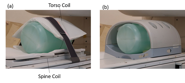
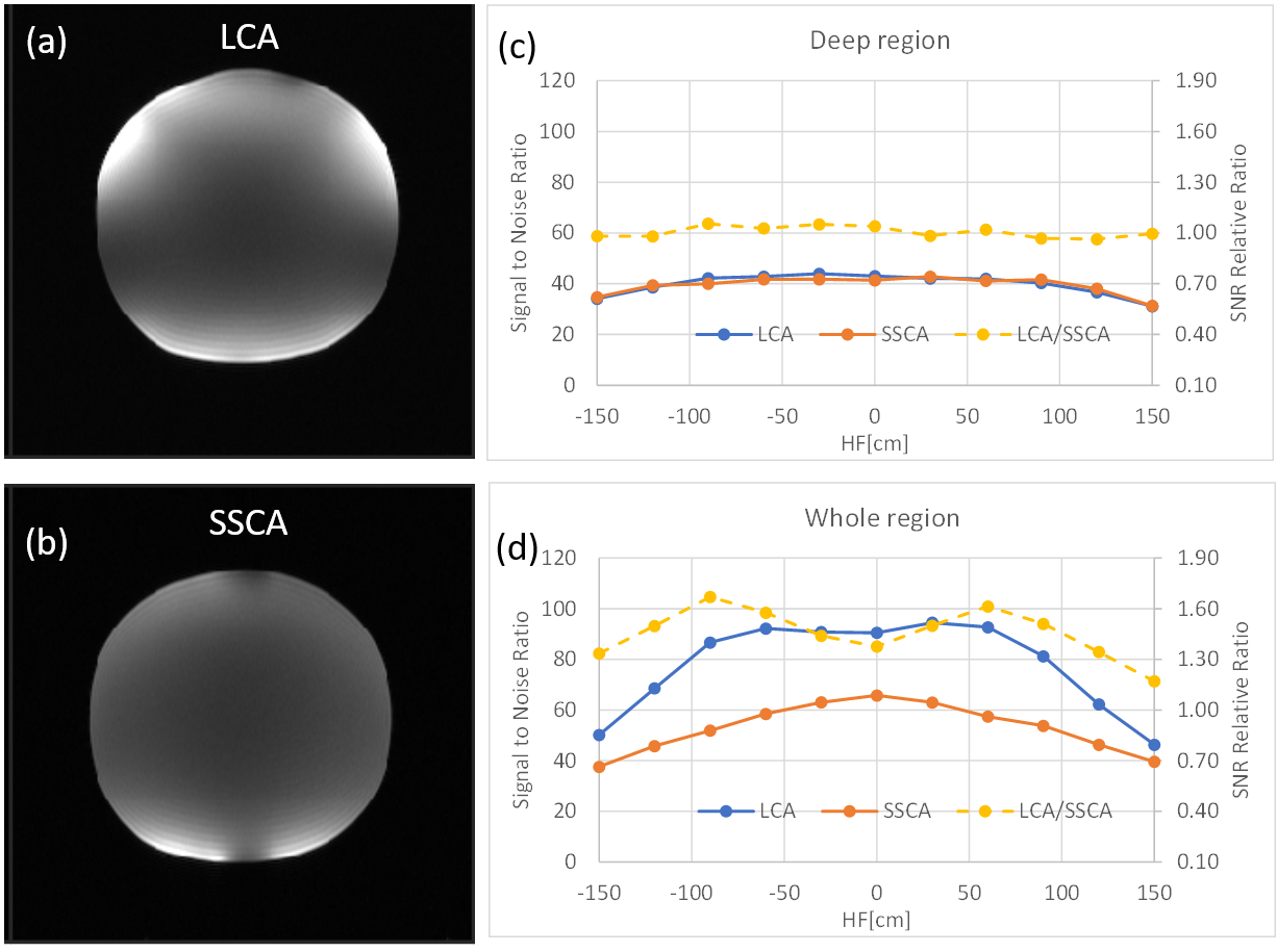
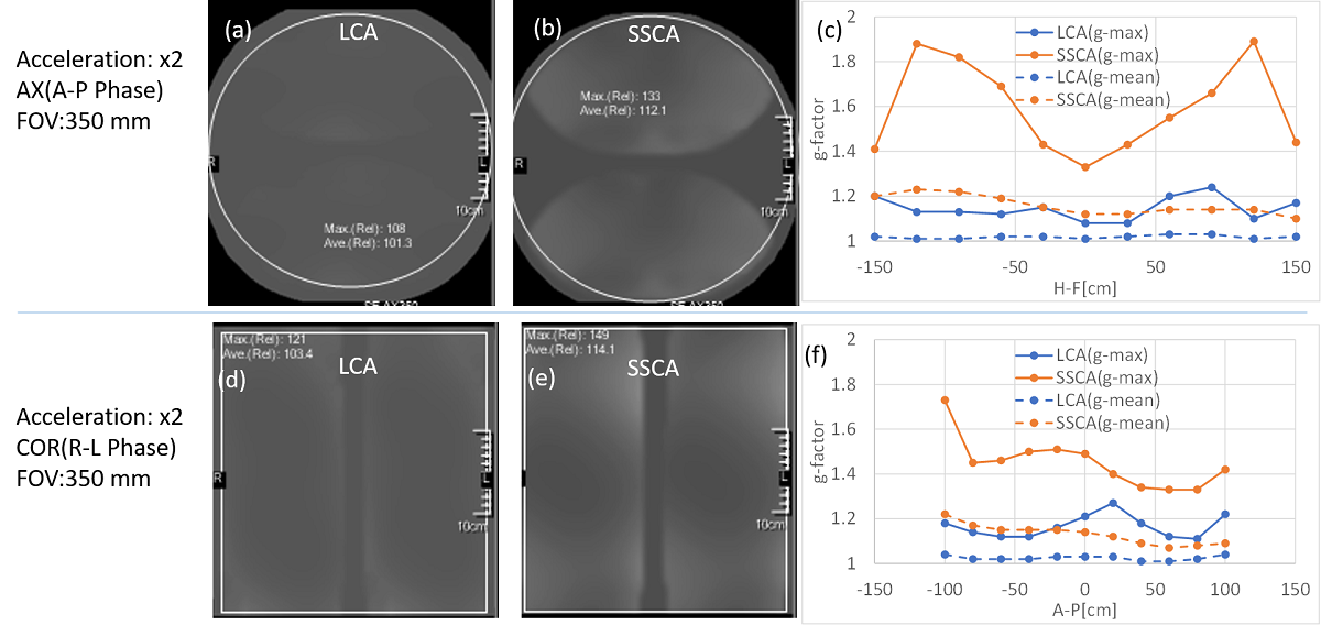
Figure 3 shows the developed body (LCA) coil and the conventional body (SSCA) coil. The usability of the developed coil was improved due to its flexibility like an array coil for the horizontal field MRI. Figure 4(a,b) shows SNR maps of the developed body coil and the conventional body coil. Fig. 4(c, d) shows the SNR line profiles of the Axial direction of cylinder in whole region (central 300-mm circular) and the deep region (central 30-mm circular area), respectively. The SNR improvement rate was shown to be 1.42 and 1.02 times in the whole area and the side area, respectively. Figure 5 shows g-factor maps of developed body coil and conventional body coil. The mean g-max improvement rate was shown to be 1.39 and 1.24 times in the AX(A-P Phase) and COR(R-L phase), respectively. These results indicate that the usability and the imaging performance of the developed coil were improved. In this study, 16 channel array coil has been developed due to the limitation of the device. However, the performance of the coil of vertical field MRI will be further improved like a horizontal field MRI by increasing multi channels over 16.Conclusion
The usability and the imaging performance of the developed coil were improved compared to the conventional coil by the LCA technique. This technique will contribute to further improving the performance of the vertical field MRI.Acknowledgements
No acknowledgement found.References
1. Roemer PB, Edelstein WA, Hayes CE, et al. The NMR phased array. Magn Reson Med. 1990 Nov; 16 (2): 192-225.
2. Hardy CJ, Giaquinto RO, Piel JE, Rohling KW, Marinelli L, Blezek DJ, Fiveland EW, Darrow RD, Foo TK. 128-channel body MRI with a flexible high-density receiver-coil array. J Magn Reson Imaging. 2008 Nov; 28 (5): 1219-25.
3. Wiggins GC, Polimeni JR, Potthast A, Schmitt M, Alagappan V, Wald LL. 96-Channel receive-only head coil for 3 Tesla: design optimization and evaluation. Magn Reson Med. 2009 Sep; 62 (3): 754-62.
4. Takizawa M, Goto T, Mochizuki H, Nonaka M, Nagai S, Takeuchi H, Taniguchi Y, Ochi H, Takahashi T. Cardiac cine parallel imaging on a 0.7T open system. Magn Reson Med Sci. 2004 Apr 1; 3 (1): 45-9.
5. Ochi H, Yamamoto E, Sawaya K, Adachi S. Calculation of electromagnetic field of an MRI antenna loaded by a body. Proceedings of the 11th Annual Meeting of SMRM, Berlin; 1992. p. 4021.
Figures
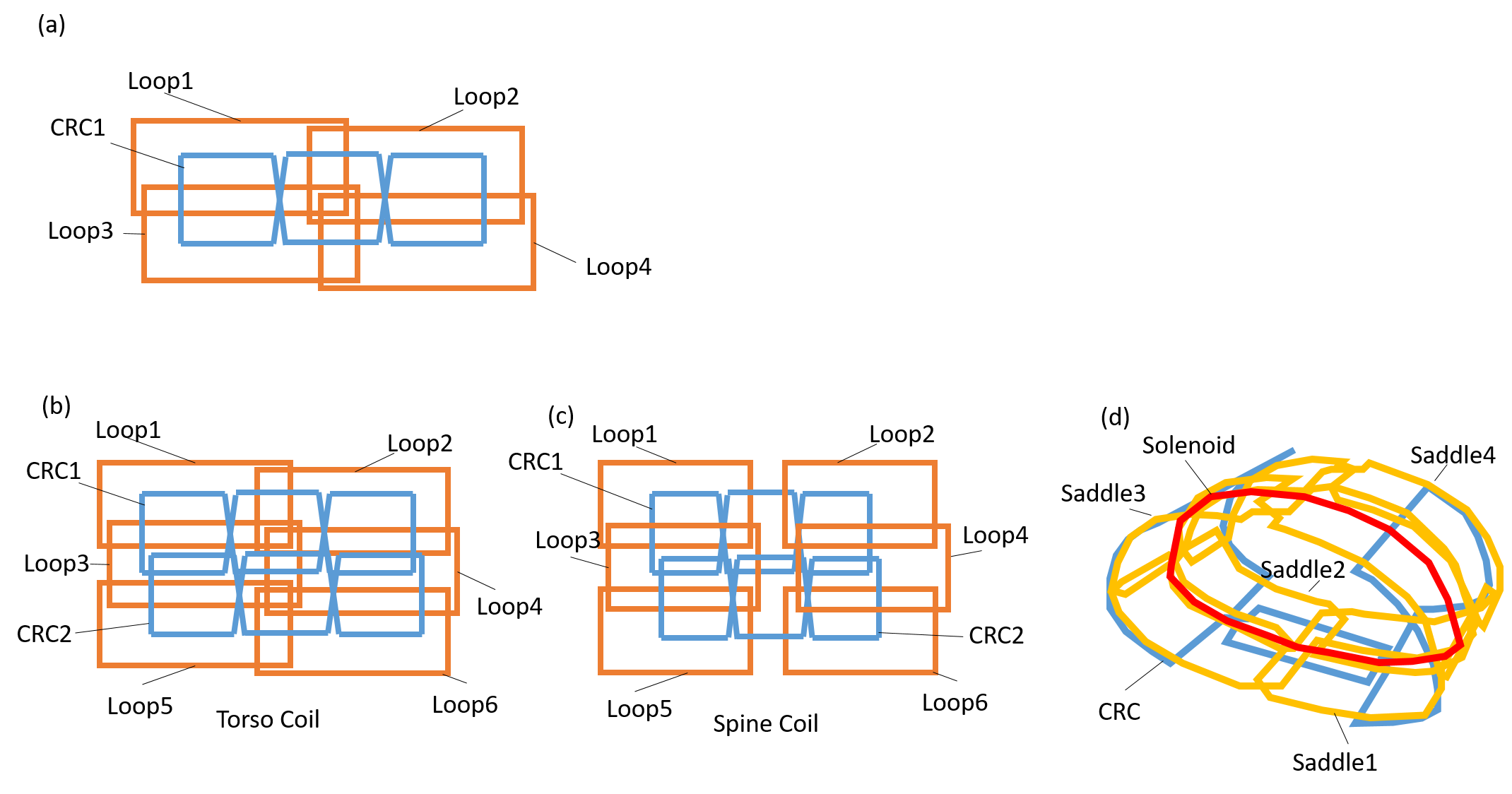
Figure 1. Coil arrangements. (a)Basic configuration of loop/CRC hybrid multi channel array (LCA) RF coil.(b)Developed torso coil using LCA(8ch). (c)Developed spine coil using LCA(8ch). (d)Conventional body coil for a vertical field MRI(6ch).