1600
Additive manufacturing of MRI coils by printing and electroplating a conductive polymer1Institute for Biomedical Engineering, ETH Zurich and University of Zurich, Zürich, Switzerland
Synopsis
In this work, additive manufacturing of MRI coils by selectively electroplating a conductive polymer is demonstrated, enabling the fabrication of complex coil geometries with high accuracy and reproducibility. Using a low-cost multi-material FDM 3D printer, deposition of insulating and conductive elements has been achieved in a single process, followed by straightforward electroplating. The proposed approach is demonstrated by an example of a wrist coil, including in-vivo imaging at 3T.
Introduction
Building geometrically complex MRI coils and arrays can be a tedious process. With conventional means, forming a prescribed 3D configuration of conductors of optimized shape and size is labor-intensive, expensive, and prone to imperfection. Additive manufacturing, in contrast, offers geometric complexity at drastically lower cost along with high levels of accuracy and reproducibility. For these reasons, 3D printing has become a valuable tool in research and development and has found its way into MRI as well. It has been used for housings [1], jigs [2], and dielectric RF field shaping [3].To deploy additive manufacturing for coil construction, it has been proposed to manually deposit colloidal palladium or silver ink on a 3D-printed plastic former followed by copper metallization [4]. However, such deposition is again tedious and also impairs accuracy and reproducibility. Furthermore, it is possible only on sufficiently accessible surfaces, limiting design choices.
In this work, we propose a more comprehensive additive-manufacturing strategy for coil making, using printable conductive polymer for selective electroplating [5]. As a proof of concept, we report the fabrication and use for imaging of an anatomically shaped wrist coil.
Methods
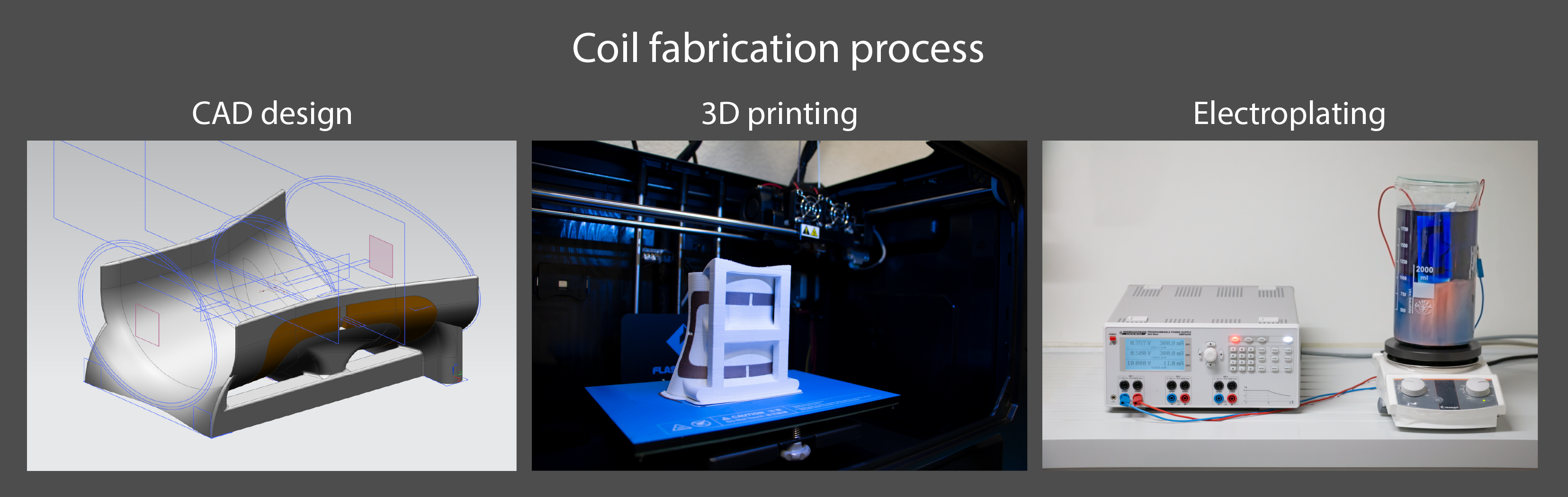
Coil fabrication is accomplished in three chief steps as shown in Fig. 1. First, a 3D model comprising conductive and insulating structures is designed with a CAD system. Second, the part is printed with a multi-material 3D printer such that no assembly is required after fabrication. Finally, all conductive polymer surfaces are coated with copper by electroplating.As conductive polymer, “Electrifi Conductive Filament” (Multi3D) was chosen while insulating sections were implemented with generic polylactic acid (PLA). The parts were printed on a Creator Pro (Flashforge) dual-extruder fused deposition modeling (FDM) 3D printer.
For copper electroplating, an aqueous electrolyte was composed of 1.0mol/l CuSO4, 0.5mol/l H2SO4, 1mmol/l NaCl, 100µmol/l polyethylene glycol, 20µmol/l Sodium 3-mercapto-1-propanesulfonate and 50µmol/l Janus Green B as described in [5]. The copper was slowly deposited with a constant current source (HMP4030, Rohde & Schwarz). After electroplating, the parts were washed in demineralized water, vacuum dried and finally coated with a thin layer of protective varnish to prevent oxidation.
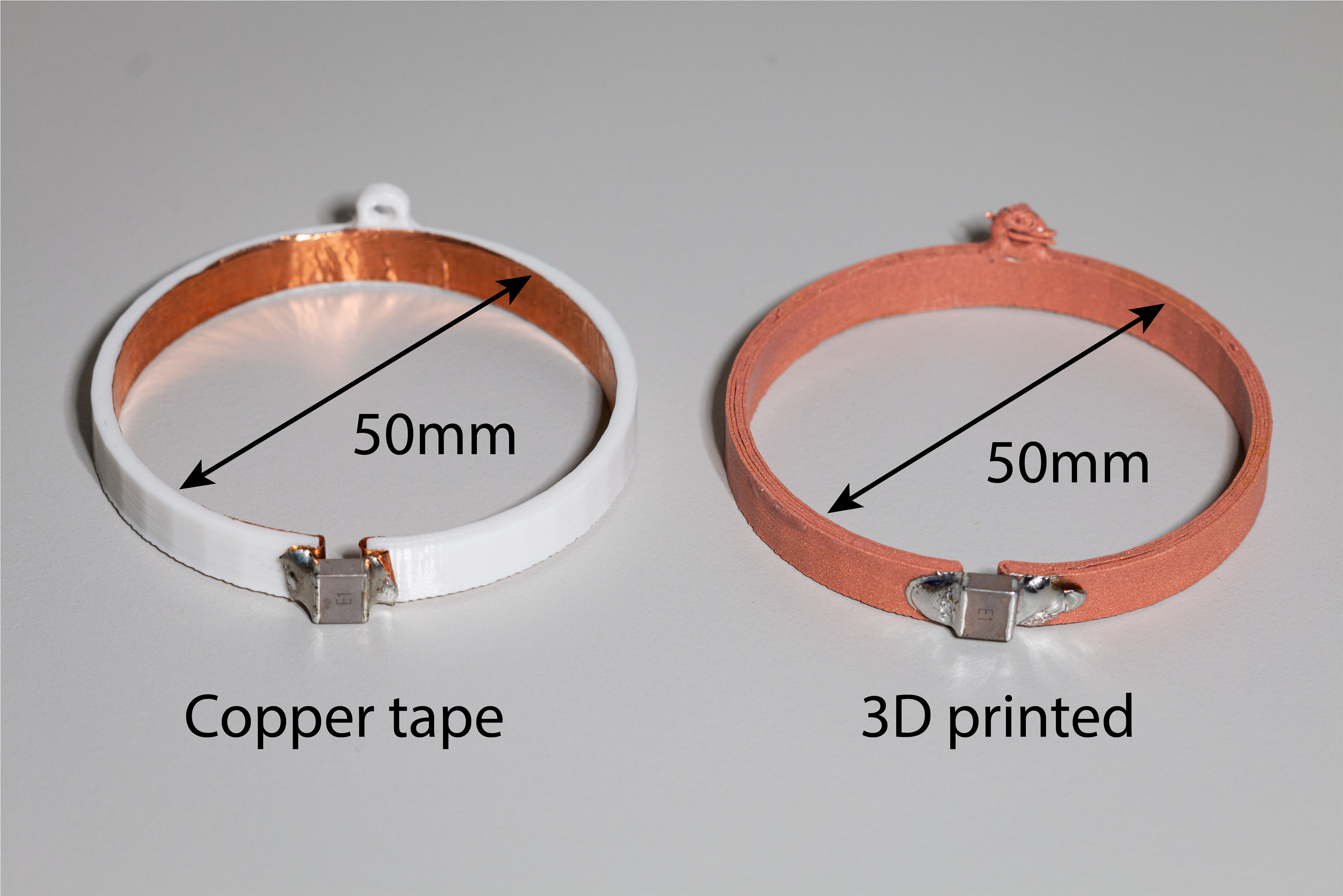
Geometric accuracy was verified by measurement with a caliper and comparison with the CAD. To assess the performance of the additively manufactured copper traces, loops with an inner diameter of 50mm were constructed (Fig. 2), one made from copper tape and one 3D printed and electroplated. With a 15pF capacitor in series, the quality factor (Q) was determined with an Aglilent E5071C network analyzer.
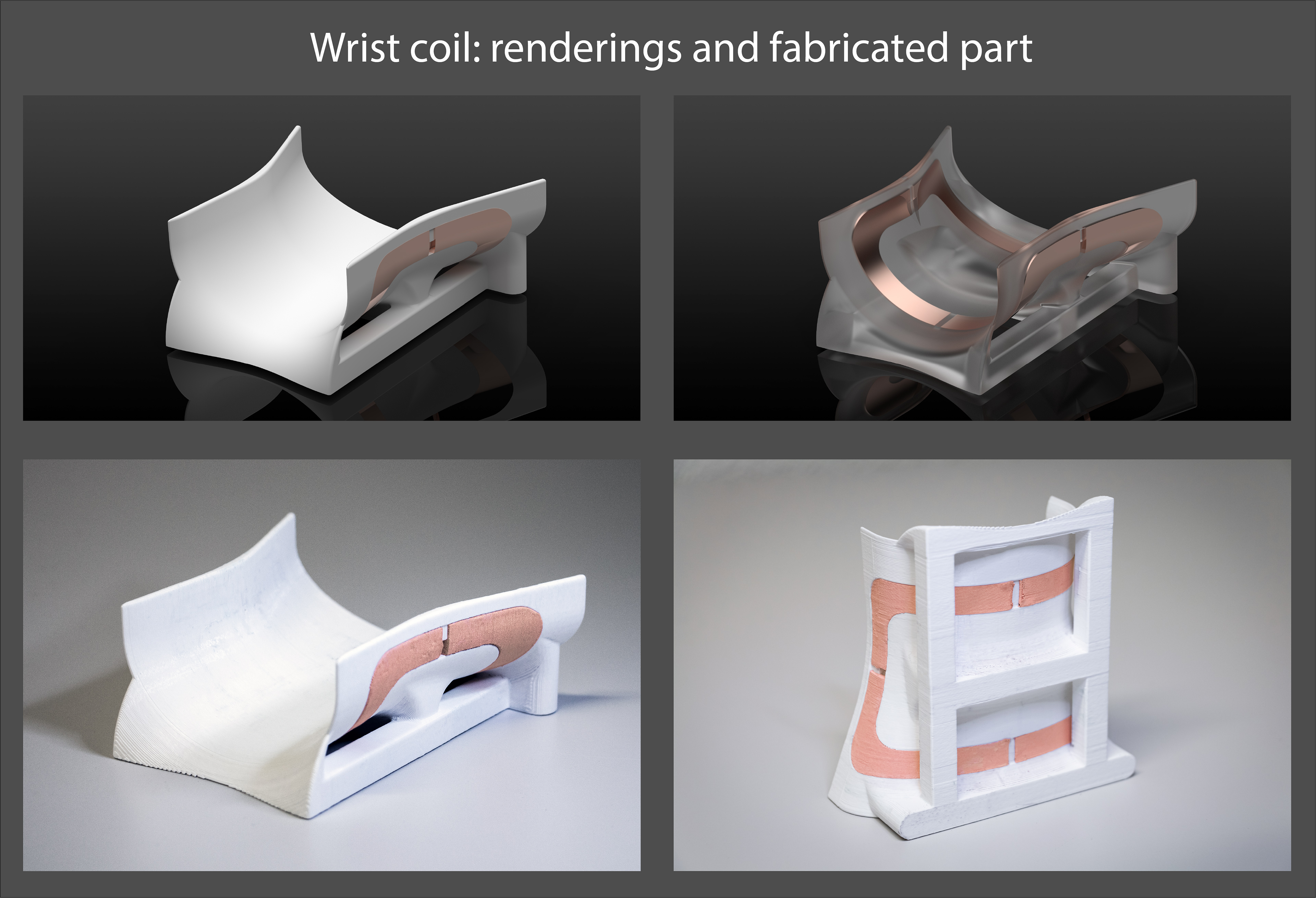
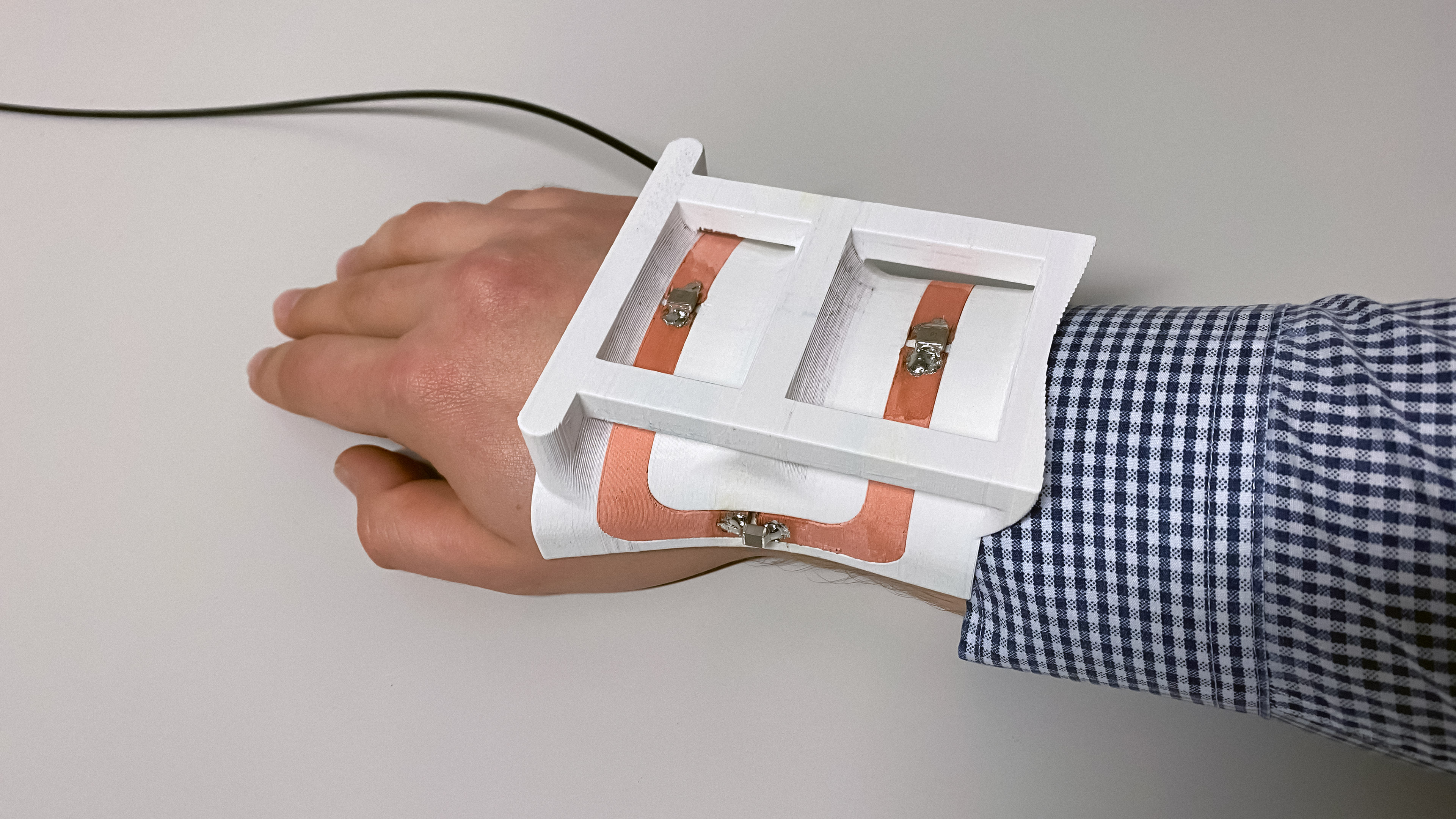
To demonstrate the feasibility of 3D-printed MRI coils, a close-fitting wrist coil was fabricated (Figs. 3, 4). The coil conductor and insulating shell were printed in one part. After electroplating, the coil was tuned to 128MHz and matched to 50Ω. Subsequent MR imaging with this coil was done on a Philips Achieva 3T scanner.
Results
The assessment of the quality factor of the 50mm loops revealed Q of 663 at 142.8MHz for the 3D-printed loop, compared with 693 at 136.2MHz of the copper-tape reference. The conductivity of the 3D-printed part was thus at least 90% of that of the reference.Verification of the geometry revealed high accuracy at a mean deviation from the CAD dimensions of around 0.1mm. The unloaded quality factor of the wrist coil was 164 and the loaded quality factor was 33, amounting to a Q ratio of 5, which corresponds to approximately 90% SNR efficiency.
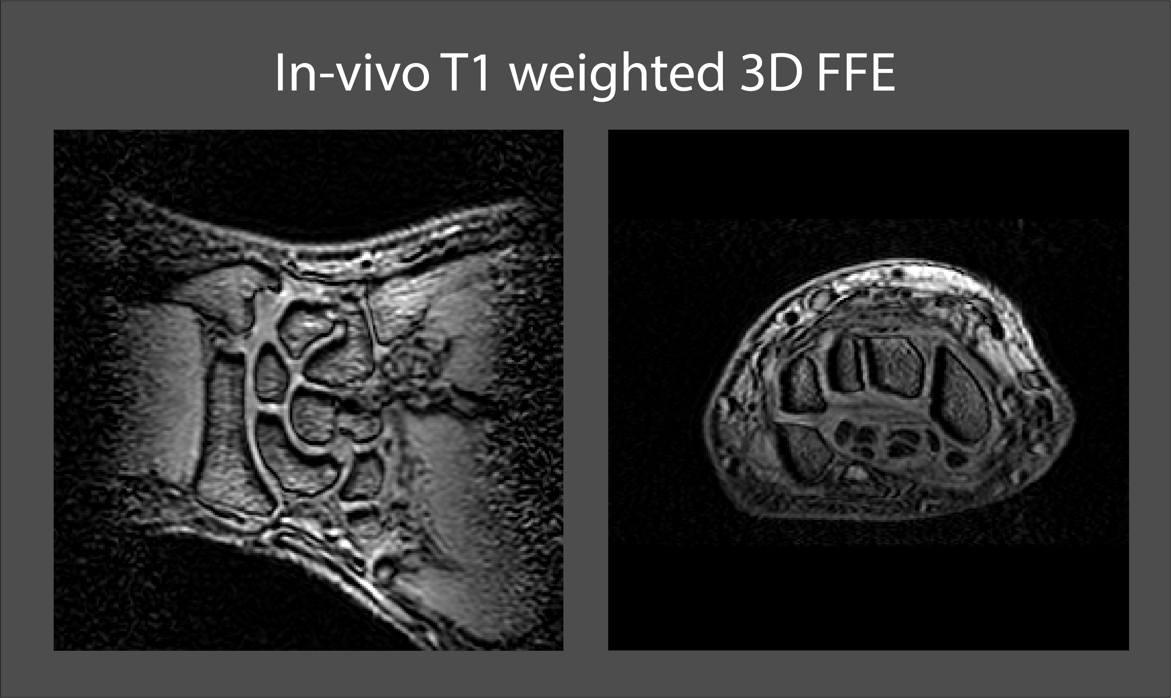
In-vivo imaging with the 3D-printed wrist coil revealed no issues and the images shown in Fig. 5 show no coil-related artefacts.
Discussion and conclusion
3D printing of conductive polymer in combination with copper electroplating has been found to permit coil fabrication fully based on additive manufacturing. Near-complete automation, high accuracy, reproducibility, and short iteration cycles make this process very attractive for MRI coil prototyping, development and, potentially, production at scale. Coil making also stands to benefit from continued rapid innovation in additive manufacturing. For instance, with more than two extruders, 3D printing could additionally include flexible material to support flexible coil arrangements.High Q factors already achieved indicate that electroplating of polymer will be competitive in terms of electrical performance. Some additional gain in conductance should be amenable by tuning of the electroplating process, which may also include electrodeposition of silver.
Regarding RF coil and array design, one highly attractive feature of digital fabrication is that it can be seamlessly combined with design optimization based on electromagnetic field simulation, even when that results in high geometric complexity.
Acknowledgements
No acknowledgement found.References
[1] S. Wei, Z. Wang, H. Wang, X. Lyu, L. Deng and W. Yang, "Design and implementation of MRI RF coil based on 3D printing," 2015 IEEE MTT-S 2015 International Microwave Workshop Series on RF and Wireless Technologies for Biomedical and Healthcare Applications (IMWS-BIO), Taipei, 2015, pp. 222-224, doi: 10.1109/IMWS-BIO.2015.7303857
[2] Karl-Heinz Herrmann, Clemens Gärtner, Daniel Güllmar, Martin Krämer, Jürgen R. Reichenbach, 3D printing of MRI compatible components: Why every MRI research group should have a low-budget 3D printer, Medical Engineering & Physics, 2014, https://doi.org/10.1016/j.medengphy.2014.06.008
[3] Bahareh Behzadnezhad, Bruce D. Collick, Nader Behdad, Alan B. McMillan, Dielectric properties of 3D-printed materials for anatomy specific 3D-printed MRI coils, Journal of Magnetic Resonance, 2018, https://doi.org/10.1016/j.jmr.2018.02.013
[4] Simon Auguste Lambert et al., Design of a volume MRI coil by metalyzing 3D printing substrates by electroless and/or electroplating processes, Proc. Intl. Soc. Mag. Reson. Med. 27 (2019)
[5] Myung Jun Kim, Mutya A. Cruz, Shengrong Ye, Allen L. Gray, Gabriel L. Smith, Nathan Lazarus, Christopher J. Walker, Hjalti H. Sigmarsson, Benjamin J. Wiley, One-step electrodeposition of copper on conductive 3D printed objects, Additive Manufacturing, 2019, https://doi.org/10.1016/j.addma.2019.03.016
Figures