1599
Performance comparison of a 10 cm single-gap vs. double-gap coaxial coil used as a transceiver for 7T MRI
Lena Nohava1,2, Andre Kuehne3, Elmar Laistler1, and Sigrun Roat1
1High Field MR Center, Center for Medical Physics and Biomedical Engineering, Medical University of Vienna, Vienna, Austria, 2BioMaps (Laboratoire d'Imagerie Biomédicale Multimodale Paris Saclay), Université Paris-Saclay, CEA, CNRS, Inserm, Orsay, France, 3MRI.TOOLS GmbH, Berlin, Germany
1High Field MR Center, Center for Medical Physics and Biomedical Engineering, Medical University of Vienna, Vienna, Austria, 2BioMaps (Laboratoire d'Imagerie Biomédicale Multimodale Paris Saclay), Université Paris-Saclay, CEA, CNRS, Inserm, Orsay, France, 3MRI.TOOLS GmbH, Berlin, Germany
Synopsis
In this work, we investigated the performance differences between a flexible single-gap coaxial coil operated far above self-resonance and a double-gap coaxial coil operated on self-resonance at 7T. Based on electromagnetic simulations and MRI results it is demonstrated that in the single-gap design the current distribution on the outside of the coaxial shield is strongly inhomogeneous. This leads to a strong dependence of the Tx performance on the coil orientation relative to B0. In contrast, the double-gap design results in homogeneous current distribution and orientation-independent Tx performance.
Introduction
Lightweight and flexible radio frequency (RF) coils allow form-fitting, wearable RF hardware designs to improve patient comfort and image quality. Ultra-flexible coaxial transmission line resonators (coaxial coils, CCs), have been employed in single-turn single-gap1–5 or multi-turn multi-gap configurations6–8 with a first self-resonance f0 very close to the target 1H Larmor frequency fL. In contrast, a 10cm single-gap (1G) CC with f0<<fL was successfully used in Tx/Rx or Rx-only mode at 7T in recent studies9,10. In this work, the goal was to simulate and experimentally investigate the difference between the operation of a 10cm 7T Tx/Rx CC on-self-resonance (f0≈fL) and off-self-resonance (f0<<fL).Methods
Analytical calculations based on the multi-gap design approach for ultra-high field (UHF) coils6,8 were performed in Matlab 2017b (The Mathworks, Natwick, USA) to determine the optimal 10cm diameter CC configuration, i.e. cable properties as well as number of gaps, with an f0≈fL, which yielded a double-gap (2G) design. 1G- and 2G-CC schematics and the fabricated CCs are shown in Fig.1a+b. Cable types differed for the 1G and 2G designs in order to replicate the 1G-CC used in references9,10 and to get a 2G-CC self-resonance as close as possible to fL (see Fig. 1b). The tuning and matching circuitry in Fig.1b was used, with either a tuning capacitor CT and parallel inductor LT (1G) or an LT only (2G). Electromagnetic (EM) simulations were carried out in CST Studio Suite 2020 (Dassault Systèmes, Paris, France). The CCs were loaded with a box-shaped phantom (40x40x25cm3, εr=80, σ=0.6S/m) at a distance of 5mm from the coils. From simulation, the unloaded f0,sim, surface current density (K = dI/dl) distribution and H- and E-field data were extracted. Post-processing in Matlab included 10g SAR averaging, calculation of transmit efficiency (B1+/√P), and inversion of the z-axis to investigate orientation dependence (Fig.1d). All simulation results were scaled to 1 W accepted input power. The inner (iCo) and outer (oCo) surface of the outer conductor (=coaxial cable shield) are separated by the skin effect (Fig.1c). Only the EM field created by the current on oCo effectively interacts with the sample. In bench and MR measurements, the coils were directly placed on the phantom shown in Fig.1d. Bench measurements of the unloaded self-resonance were performed using a VNA (E5071C, Agilent, Santa Clara, CA, USA) and a decoupled dual-loop probe11. Measurements including the coil interface were conducted via a 50Ω connection to the VNA. In MRI, for both coils and two investigated coil port orientations (Fig.1b+d), the transmit efficiency was assessed based on acquired FA maps (saturated TurboFLASH method12).Results
Both coils were sufficiently matched, and Q ratios listed in Tab.1 indicate clear sample noise dominance. EM simulation results depicted in Fig.2 show that at 297.2MHz, the loaded 1G-CC has an oCo surface current maximum at the iC gap, i.e. the coil port. In the 1G-CC, the mean oCo surface current along the whole loop is 6.8% lower and the current distribution is more inhomogeneous - as compared to the 2G-CC. Point SAR simulations given in Fig.3 show increased values for the 1G-CC, resulting in 11% higher 10g average SAR. Transmit efficiency maps derived from MR experiments and simulations are depicted in Fig.4. It is demonstrated that for the 1G-CC, operating off-resonance (f0<<fL), the Tx performance strongly depends on the coil port orientation. In orientation 1, the higher B1+ lobe close to the coil conductor due to the typical UHF asymmetry and the part of the 1G-CC carrying the higher current coincide, resulting in even slightly deeper penetration depth at this location than with the 2G design. However, in opposite orientation 2, the lower B1+ lobe and the high-current part coincide, leading to reduced Tx efficiency as compared to the 2G-CC. The 2G-CC showed almost identical Tx performance in both orientations due to the homogeneous oCo current distribution.Discussion
The inhomogeneous 1G-CC oCo current distribution resembles the ones intentionally created in rigid copper “loopole” (loop+dipole)13 or “self-decoupled”14 coil designs using unequally distributed capacitors. Magnetic and electric coupling contributions between neighboring loops could potentially be cancelled between 1G-CCs in analogy to work in reference14. This may be an explanation for the reported improved decoupling in coaxial coils9,10,15. Presumably, with more pronounced dipole-like currents, larger penetration depths for 1G-CCs could be reached. This is only advantageous if the 1G-CC is employed in either Tx- or Rx-only mode as the performance depends on the coil port location: for Rx the optimal orientation of the 1G-CC is opposite to the Tx case due to the UHF B1 asymmetry. Strong Lorentz forces were experienced with 1G-CCs when moving the coil inside the scanner, which can be explained by the unsegmented loop of the inner conductor. This has to be considered in wearable coils, e.g. with elements loosely attached to the support material. For the 2G design, no Lorentz forces were observed, since the loop is separated by a gap.Conclusion
Based on EM simulations and MRI data we conclude that the double-gap coaxial design, i.e. more generally operating the coil on-self-resonance, is advantageous for robust coil performance with arbitrary orientation relative to B0. The 10cm diameter 2G-CC could be employed in arrays for knee, head or abdomen imaging.Acknowledgements
This project was funded by the Austrian/French FWF/ANR grant, Nr. I-3618, “BRACOIL“.References
- Zhang, B., Sodickson, D. K. & Cloos, M. A. A high-impedance detector-array glove for magnetic resonance imaging of the hand. Nat. Biomed. Eng. 2, 570–577 (2018).
- Urayama, S.-I., Zhang, B., Fujimoto, K., Okada, T. & Cloos, M. A. A modular 7T high-impedance array for ex-vivo imaging. in Proc. Intl. Soc. Mag. Reson. Med. 27 (2019), p. 1541.
- Zijlema, S. E., Van Dijk, L., Lagendijk, J. J. W., Tijssen, R. H. N. & Van Den Berg, C. A. T. A radiolucent and flexible high impedance coil array to improve the imaging performance of a 1.5T MR-linac. in Proc. Intl. Soc. Mag. Reson. Med. 27 (2019), p. 1504.
- Obermann, M. et al. Ultra-flexible and light-weight 3-channel coaxial transmission line resonator receive-only coil array for 3T. in Proc. Intl. Soc. Mag. Reson. Med. 27 (2019), p. 1558.
- Fujimoto, K. et al. A tight-fit flexible high-impedance coil array for high-resolution imaging of small ex-vivo specimen using a human 7T scanner. in Proc. Intl. Soc. Mag. Reson. Med. 28 (2020), p. 4018.
- Nohava, L. et al. Flexible multi-turn multi-gap coaxial RF coils (MTMG-CCs): design concept and bench validation. in Proc. Intl. Soc. Mag. Reson. Med. 27 (2019), p. 565.
- Nohava, L. et al. Flexible receive-only coaxial coils with multiple turns and gaps for 3 T MRI. in Proc. Intl. Soc. Mag. Reson. Med. 28 (2020), p. 750.
- Nohava, L. et al. Flexible transmit/receive multi-gap coaxial coils for 7 T MRI. in Proc. Intl. Soc. Mag. Reson. Med. 28 (2020), p. 4273.
- Ruytenberg, T., Webb, A. & Zivkovic, I. A flexible five-channel shielded-coaxial-cable (SCC) transceive neck coil for high-resolution carotid imaging at 7T. Magn. Reson. Med. 84, 1672–1677 (2020).
- Ruytenberg, T., Webb, A. & Zivkovic, I. Shielded-coaxial-cable coils as receive and transceive array elements for 7T human MRI. Magn. Reson. Med. 83, 1135–1146 (2020).
- Darrasse, L. & Kassab, G. Quick measurement of NMR-coil sensitivity with a dual-loop probe. Rev. Sci. Instrum. 64, 1841–1844 (1993).
- Chung, S., Kim, D., Breton, E. & Axel, L. Rapid B1+ mapping using a preconditioning RF pulse with TurboFLASH readout. Magn. Reson. Med. 64, 439–446 (2010).
- Lakshmanan, K. et al. The “Loopole” Antenna: A Hybrid Coil Combining Loop and Electric Dipole Properties for Ultra-High-Field MRI. Concepts Magn. Reson. Part B, Magn. Reson. Eng. 2020, 8886543 (2020).
- Yan, X., Gore, J. C. & Grissom, W. A. Self-decoupled radiofrequency coils for magnetic resonance imaging. Nat. Commun. 9, 3481 (2018).
- Mollaei, M. S. M., Van Leeuwen, C. C., Raaijmakers, A. J. E. & Simovski, C. R. Analysis of High Impedance Coils Both in Transmission and Reception Regimes. IEEE Access 8, 129754–129762 (2020).
Figures
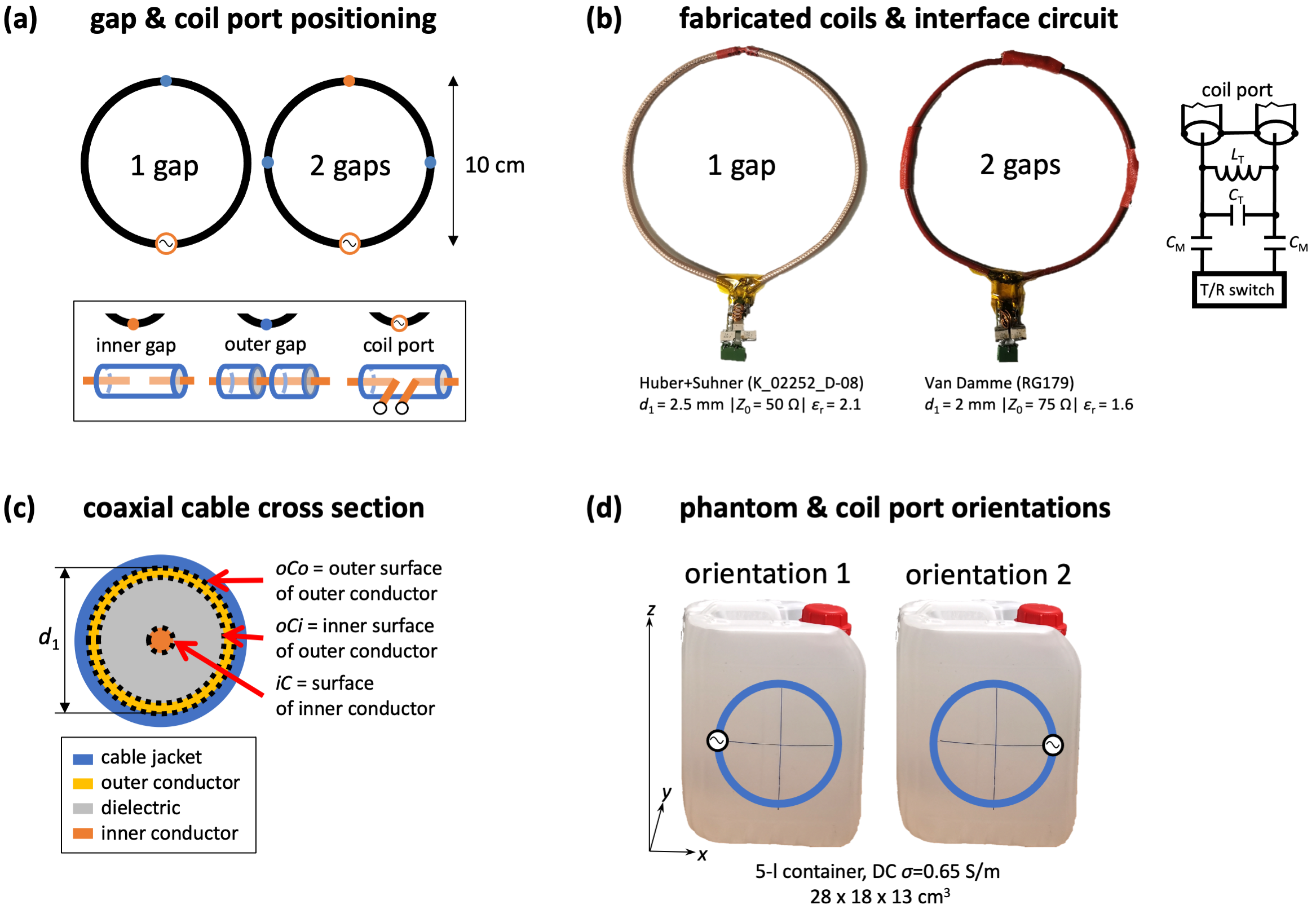
Figure 1: (a) Schematic showing gap positioning, (b) photographs of fabricated coils and interface circuit, (c) coaxial cable cross section, (d) phantom photo and investigated coil orientations.
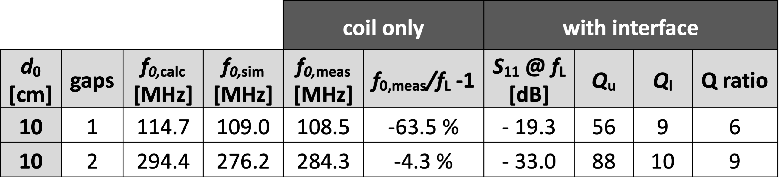
Table 1: Analytical calculation (f0,calc), simulation (f0,sim) and bench measurement (f0,meas) results with the coil only or with interface. Qunloaded (Qu) values at fL were extrapolated from unloaded measurements at around 350-370 MHz.
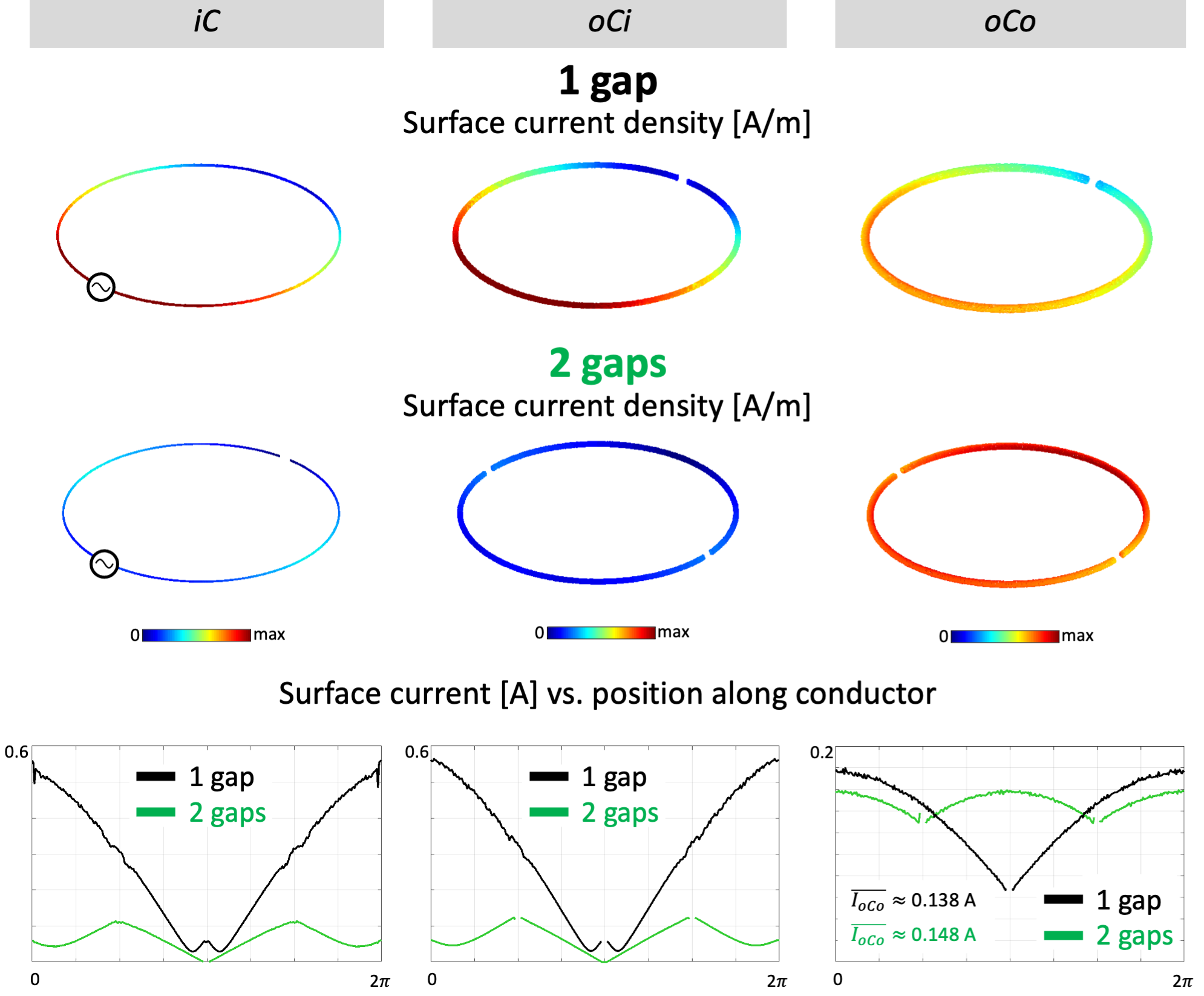
Figure 2: EM simulation results for a loaded single-gap (top) and double-gap (middle) coaxial coil. 3D surface current density plots (bottom) are scaled to the maximum value on the iC (surface of the inner conductor), iCo (inner surface of the outer conductor) or oCo (outer surface of the outer conductor).
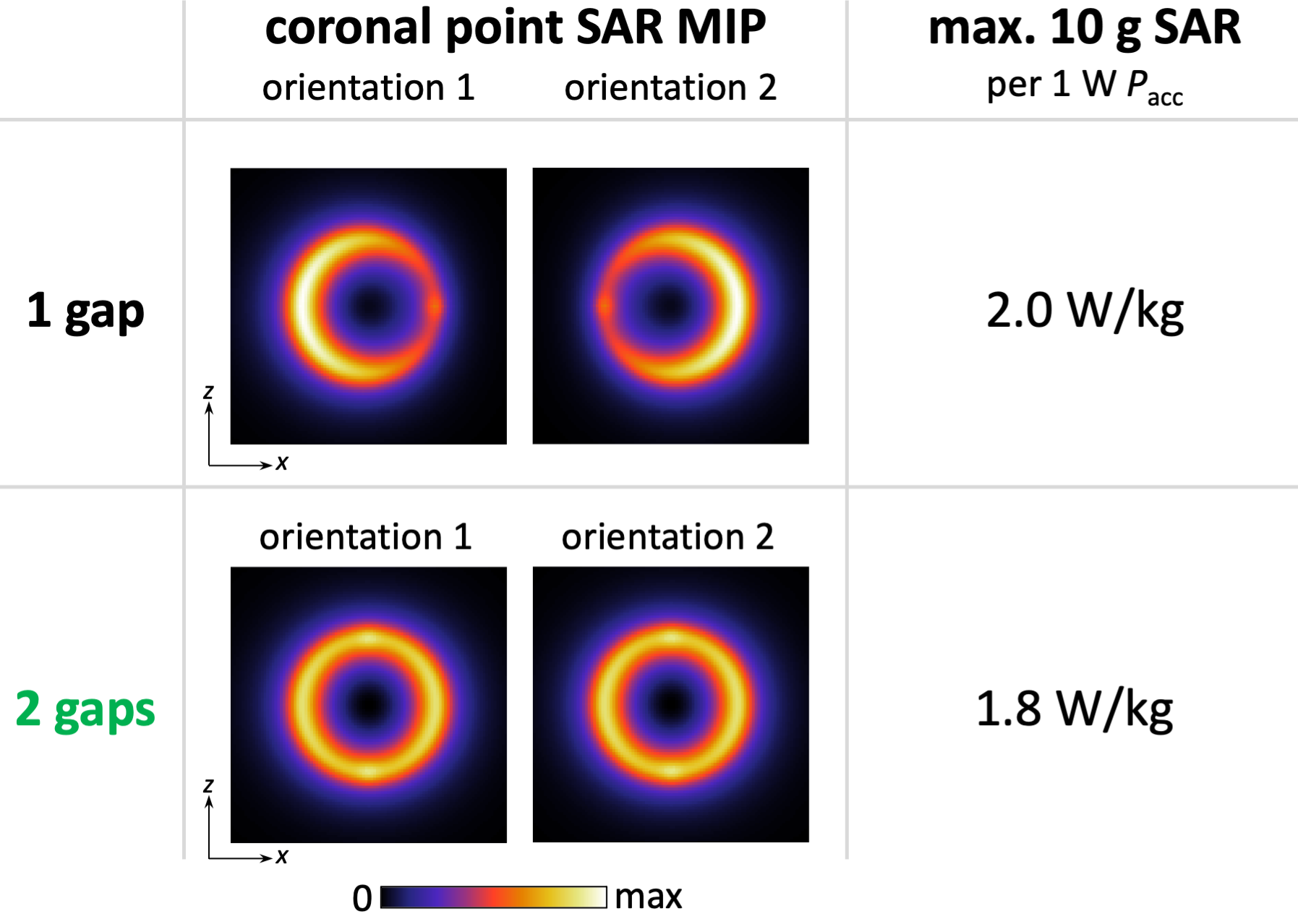
Figure 3: Coronal point SAR maximum intensity projections (MIPs) and maximum local 10g SAR values.
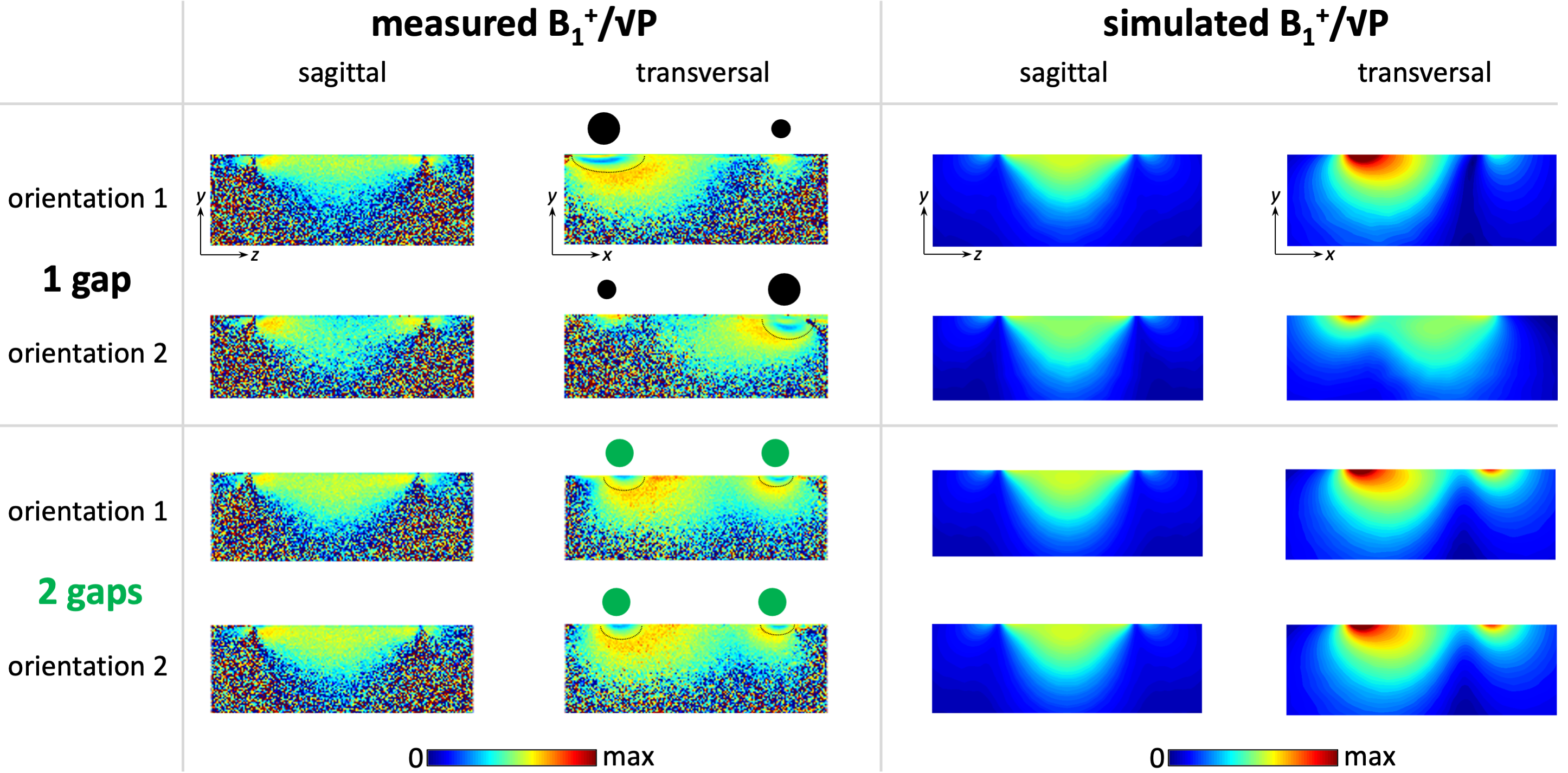
Figure 4: Measured and simulated B1+/√P maps in the central sagittal and transversal slice (FOV=256x256mm2, 0.5x0.5mm2 in-plane resolution, 1.5mm slice thickness, Vref=150V). Different orientations are indicated by black or green dots: their location corresponds to the coil conductor position and their size indicates the oCo current density (inhomogeneous for the 1G, homogeneous for the 2G coil). Thin black lines in transversal measured maps mark the boundaries of regions where the flip angle was higher than the dynamic range of the mapping technique.